Manually Configuring a Segment Topology
To view the segments that are manually configured, follow the Infrastructure ->Segments ->Configured option. This results in Figure 1 where the segment list that pre-exists can be viewed. To modify a segment, click on the  icon corresponding to that segment in Figure 1. To delete a segment, click the
  icon corresponding to it. To delete multiple segments simultaneously, select the check box against each segment and click the
  icon. To delete all the segments configured in the infrastructure, select the check box against the Segment Name label and click the icon.
If a large number of segments have been configured, locating the segment to be modified/deleted would become quiet a challenge. This page therefore allows you to quickly search for a segment, by first specifying the whole/part of the segment name in the Search text box, and then clicking the  icon next to the text box. All segments with names that embed the specified string will then appear.
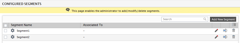
Figure 1 : Currently configured segments in the environment
You can even change the name of a segment by clicking the  icon corresponding to it. Provide the New name for the selected segment in Figure 2 that appears and click the Rename button therein to register the new name. This will automatically change the segment name across the eG user interface.
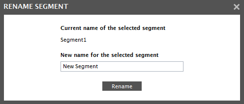
Note:
Since renaming changes the name of a segment across the user interface, you will no longer be able to access performance data of the segment for the period prior to the name-change using the monitoring/reporting consoles. Therefore, exercise caution when renaming a segment.
A new segment can be added by using the Add New Segment button as shown in Figure 1. The screen depicted by Figure 3 appears. Here, to add a new segment, specify the name of the segment in the Segment name text box.
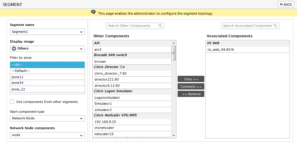
Figure 3 : Adding a new segment
Next, select a Display image for the segment.
If you want your segment to contain a component that is already within a zone, then select that zone from the Filter by zone list. By default, the --All-- option is displayed indicating that all components in the monitored infrastructure are available for creating a new segment.
By default, components that are already a part of other segments will not be available for inclusion in a segment. However, if a single component features in multiple segments, this default setting can be overridden - i.e., while configuring such segments, you can switch on the Use components from other segments flag in Figure 3. By default, this check box is deselected. By selecting it, you can ensure that components that are already a part of other segments are also available for inclusion in the new segment.
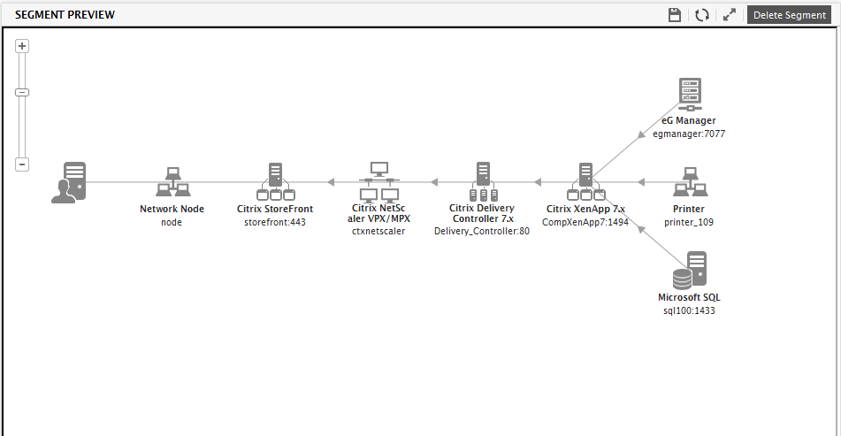
Figure 4 : Preview of the configured segment topology
The interconnections between components of a segment must be configured from left-to-right, with the left most node(s) representing the entry points through which users access the web services offered in the target environment. As is evident from Figure 4, the segment is configured step-by-step, with all the dependencies of one of the components in the environment/zone being specified at each step. Using the Start component type and the components list that follows it, select the component type and the component (of that type) with which the dependency begins. Then, from the Other Components list, select the component with which the dependency ends. In other words, if a web server is dependent on an Oracle database server for its functioning, then select the web server component using the Start component type and the components list, and pick the Oracle database server from the Other Components list. Then, pick the type of dependency that binds the chosen components by clicking one of the two buttons – Uses or Connects. Figure 4 indicates that eG Enterprise supports two types of dependencies: the Connects dependency, which typically indicates flow of data (e.g., a physical connection between a web server and a network router), and the Uses dependency, which refers to a logical dependency (e.g., a web server and a web application server, a web application server and a database server, etc.). The key difference between the two forms of dependencies is that when one component Uses another, problems with the latter component can actually reflect in problems with the former component. With the Connects dependency, there are no such cause-effect relationships between the two components. This way, build the entire segment topology.
Figure 4 depicts the topology graph of a segment configured via the user interface. In this example, users access the target environment via a network node. The network node is connected to a Citrix Storefront. The storefront server forwards incoming client requests to a Citrix NetScaler, which in turn routes the requests to a Delivery Controller 7.x. The Delivery controller then routes the requests to XenApp 7.x server in the farm. A Microsoft SQL server, Printer and an eG Manager are used in the backend to provide support services.
Note:
- All the components that are not a part of any segment are considered as independent components.
- An independent component can be added to more than one segment.
- Only managed component-types are available in the Type of components list box.
The Delete Segment button in Figure 5 enables the administrators to delete any configured segment. At each step, as the dependencies are specified by the administrator, the segment preview as in Figure 5 displays the current segment configuration. The feedback provided by the segment preview can be used by the administrator to refine the segment specification.
The Remove option in Figure 4 can be used to delete any of the configured dependencies from the segment.
While the topology depicted by Figure 5 is fairly small and simple, large, mission-critical environments, on the other hand, are characterized by several load balanced groups of servers providing web, middleware, and database functionality. The servers in the group often perform the same functions and have the same set of dependencies on other infrastructure components. For a segment with tens of servers in a group, the segment topology representation can quickly get very cumbersome. To handle such environments, eG Enterprise allows the configuration of Groups. By grouping all components that share the same inter-relationships in a topology as one, administrators can ensure that large topology representations do not appear cluttered! To know how to configure Groups, refer to Section . To know how to use a Group in a topology configuration, let us once again consider the Segment1 topology depicted by Figure 5 above. As you can see the Citrix XenApp server in the topology supports a Uses dependency with the following components:
- A Microsoft SQL server
- A Printer
- An eG Manager
Let’s say that these 4 components have been grouped under a group named new_group. Now, to build this group into the topology, do as follows:
-
Since it is the Citrix XenApp server that is dependent on the group, first select Citrix XenApp from the Start component type list, as depicted by . Then, select the XenApp server from the Citrix XenApp components list.
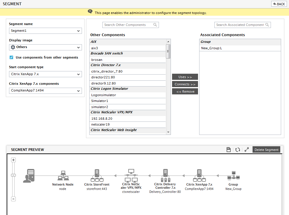
Figure 5 : Selecting the group to be included in a segment topology
- The group, New_Group, will now appear in the other components list. To associate the group with the Citrix XenApp 7.x server, select it from the other components list, and click the Uses button.
-
The segment preview depicted by clearly indicates that the group, New_Group, has been associated with the Citrix XenApp 7.x server.
Moreover, in order to help you view and analyze the configured topology better, the segment preview section (see ) provides a special toolbar comprising of easy-to-use viewing options. These options have been discussed in the table below:
Tool Purpose 
Helps to zoom in and zoom out the topology representation

You can change the position of any server representation in your topology by clicking, dragging, and dropping that representation. Once done, you can click on this icon to save the change in position.

As stated earlier, you can reposition any component in the segment preview by clicking on it and dragging it to the desired position. To restore the component(s) so shifted to their original positions, click on this icon.

Click here to view the topology in a new window.