Configuring Geo Locations
In multi-user environments - eg., environments hosting business-critical web applications, application delivery platforms, VDI environments etc. - it is important for administrators to ensure that user experience with the target environment is above par at all times. This is because, poor user experience not just impacts the productivity of users, but also disrupts key business operations, and consequently, revenues. By proactively identifying users with a sub-par experience and accurately diagnosing the reason for the same, such disasters can be averted.
Knowing where a user comes from can greatly help in understanding and diagnosing the cause of poor user experience with such environments. This is why, eG Monitors that focus on multi-user environments, namely - the eG Real User Monitor (RUM), the eG Citrix Virtual Apps/VDI Monitor, and the eG
To perform automatic location discovery, these eG Monitors use the Maxmind GEO IP2 City by default. The key limitation of Maxmind is that it can be used to determine the geographic location of only those users who access a monitored environment via the internet. For capturing the geography of intranet users on the other hand, the eG Monitors require a Geo Location Mapper file. This is typically an XML file, where the intranet IP ranges and the geography they represent need to be manually specified. To help administrators easily and quickly create such geo location mapper files and associate them with the relevant eG Monitors, eG Enterprise provides the GEO LOCATIONS interface.
To access this interface, follow the Agents->Geo Locations menu sequence in the eG admin interface.
Doing so will invoke Figure 4.
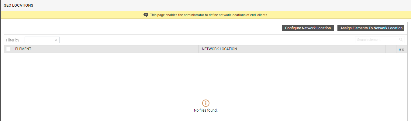
Figure 4 : A message indicating that no network locations have been configured
With the help of Figure 4, you can do the following:
-
Configure a new geographic location by creating a geo location mapper XML file, and upload it to the eG manager;
-
Associate the location so configured with an eG Monitor, so the said Monitor can download the XML file that corresponds to that locations and uses it to compute the location of intranet users
The sub-sections that follow will discuss each of the above-mentioned steps elaborately.
Configuring New Network Locations
Follow the steps below to configure geo locations using Figure 4:
-
If one/more network/geographic locations have already been configured for intranet users, then Figure 4 will display these locations. If not, then a message to that effect will be displayed (as shown by Figure 4). To configure a new location, click on the Configure Network Location button in Figure 4.
-
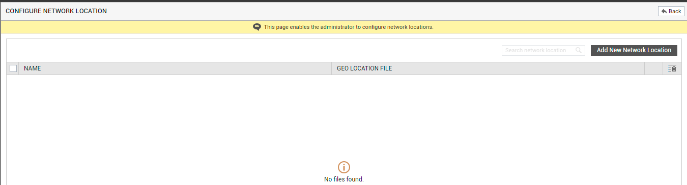
Figure 5 will then appear. To add a new network location, click on the Add New Network Location button in Figure 5.
-
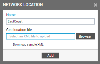
Figure 6 then pops up. Let us use an example to help you understand how to configure a new geographic location. Assume that your enterprise has offices in the East Coast of USA, with a branch in Boston. The Boston branch spans three different buildings, namely - North Building, South Building, and East Building. Each building is in a different network. Users from these buildings communicate with your web site over the intranet. To configure a geo location mapper XML file for the East Coast, first specify the Name of the new location you are creating (see Figure 6) - say, EastCoast.
-
Then, proceed to specify the location of the mapper file, where the IP ranges of every building in the East Coast are specified. In the case of our example however, this mapper file is yet to be created. Therefore, first click on the Download sample XML link in Figure 6. A geolocation-sample.xml file will then get downloaded to the local host. Open this XML file in a text/XML editor. You need to configure the IP ranges in your geography in this XML file only. This can be performed in one of the following ways:
-
By configuring the starting IP and ending IP address of each range, OR;
-
By configuring the starting IP address and the sub-net mask of each range.
-
-
If you know the starting and ending IP addresses of every network, then go with the first option - i.e., configure the starting and ending IP addresses of every network in the geolocation-sample.xml file to indicate the geographic location. In this case, do the following:
-
Scroll down the geolocation-sample.xml file until the following sample code block comes into view:
<location start-ip-address="192.168.8.1" end-ip-address="192.168.8.150">
<country>India</country>
<region>Tamil Nadu</region>
<city>Chennai</city>
<country-code>IN</country-code>
<latitude>13.0827</latitude>
<longitude>80.2707</longitude>
</location>
-
Edit this code block to suit your needs. For instance, assume that the starting and ending IP addresses of every building in our example is as follows:
Starting IP address
Ending IP address
Building
192.168.8.1
192.168.8.250
North Building
192.168.9.1
192.168.9.250
South Building
192.168.10.1
192.168.10.250
East Building
-
Now, alter the sample code block to configure the location of the North Building. For this, you need the change the values contained within the <location>, <country>, <region>, <city>, <country-code>, <lattitude>, and <longitude> XML tags, as indicated below:
Tag
Description
Value
<location start-ip-address=
The IP address with which the IP range of the North Building begins
192.168.8.1
end-ip-address=
The IP address with which the IP range of the North Building ends
192.168.8.250
<country>
The country to which the North Building belongs
USA
<region>
The region in which the North Building is situated
East Coast
<city>
The city in which the North Building stands
Boston
<country-code>
The custom code using which you want to represent the North Building - in the case of our example, let us use the code 'NB'
NB
<lattitude>, <longitude>
The co-ordinates that at least approximately indicate the location of the North Building. The RUM, VDI, and User Experience dashboards in the eG monitoring console include Geo Maps, where the user locations are visually indicated. These co-ordinates help compute and indicate the locations for intranet users in the Geo Maps. You can use any Lattitude/Longitude finder (eg., https://www.latlong.net/) to determine the co-ordinates for any location.
lattitude=42.360081
longitude=-71.058884
The edited code block will be as shown below:
<location start-ip-address="192.168.8.1" end-ip-address="192.168.8.250">
<country>USA</country>
<region>East Coast</region>
<city>Boston</city>
<country-code>NB</country-code>
<latitude>42.360081</latitude>
<longitude>-71.058884</longitude>
</location>
-
Similarly, you need to configure a code block for the South Building, and another for the East Building. For this, you need to insert two other <location> code blocks below the one that you have just configured for the North Building. The code blocks for the South and East Buildings will look like this:
<location start-ip-address="192.168.9.1" end-ip-address="192.168.9.250">
<country>USA</country>
<region>East Coast</region>
<city>Boston</city>
<country-code>SB</country-code>
<latitude>42.360085</latitude>
<longitude>-71.058890</longitude>
</location>
<location start-ip-address="192.168.10.1" end-ip-address="192.168.10.250">
<country>USA</country>
<region>East Coast</region>
<city>Boston</city>
<country-code>EB</country-code>
<latitude>42.360090</latitude>
<longitude>-71.058895</longitude>
</location>
From the <country-code> tag highlighted in the code blocks above, it is clear that the custom codes 'SB' and 'EB' have been assigned to the South and East Buildings, respectively. Also, note that the values of the <country>, <region>, and <city> XML tags in both the code blocks above are the same as that of the code block for the North Building. This is because, all 3 buildings are in the same city, region, and country. However, you will find that there is a marginal change in the values of the <lattitude> and <longitude> tags in the 3 code blocks.
-
Now that the locations we need have been configured, save the sample file, but in a different name, anywhere in the local host.
-
-
On the other hand, if you do not know the ending IP addresses, then you can have the eG Enterprise system automatically compute the IP address range of each of your networks. For this, you need to go with the second option - i.e., configure the starting IP address and sub-net mask of each of your networks. In this case, follow the steps below:
-
Assume that the starting IP address and subnet-mask of each building in our example is as follows:
Network IP Range
Subnet-mask
Building
192.168.8.0
255.255.254.0
North Building
192.168.9.0
255.255.254.0
South Building
192.168.10.0
255.255.254.0
East Building
-
Next, open the geolocation-sample.xml file that you downloaded at step 4 above in a text/XML editor. Search the file for the text, 'Option 2'. Once you find it, scroll down further, so the following code block comes into view:
<!--
<location network="192.168.10.1" subnet-mask="255.255.254.0">
<country>United States</country>
<region>California</region>
<city>Los Angeles</city>
<country-code>US</country-code>
<latitude>34.0522</latitude>
<longitude>118.2437</longitude>
</location>
-->
-
To use this code block, first 'uncomment' it by removing the <!-- and -->, within which the code block is contained. Then, proceed to edit the block, to configure it with the location of the North Building in our example. For this, you need the change the values contained within the different tags in the sample code block, as indicated below:
Tag
Description
Value
<location network=
The IP address with which the IP range of the North Building begins
192.168.8.1
subnet-mask=
The subnet mask of the new location
255.255.254.0
<country>
The country to which the North Building belongs
USA
<region>
The region in which the North Building is situated
East Coast
<city>
The city in which the North Building stands
Boston
<country-code>
The custom code using which you want to represent the North Building - in the case of our example, let us use the code 'NB'
NB
<lattitude>, <longitude>
The co-ordinates that at least approximately indicate the location of the North Building. The RUM, VDI, and User Experience dashboards in the eG monitoring console include Geo Maps, where the user locations are visually indicated. These co-ordinates help compute and indicate the locations for intranet users in the Geo Maps. You can use any Lattitude/Longitude finder (eg., https://www.latlong.net/) to determine the co-ordinates for any location.
lattitude=42.360081
longitude=-71.058884
The edited code block will be as shown below:
<location network="192.168.8.0" subnet-mask="255.255.254.0">
<country>USA</country>
<region>East Coast</region>
<city>Boston</city>
<country-code>NB</country-code>
<latitude>42.360081</latitude>
<longitude>-71.058884</longitude>
</location>
-
Similarly, you need to configure a code block for the South Building, and another for the East Building. For this, you need to insert two other <location> code blocks below the one that you have just configured for the North Building. The code blocks for the South and East Buildings will look like this:
<location network="192.168.9.0" subnet-mask="255.255.254.0">
<country>USA</country>
<region>East Coast</region>
<city>Boston</city>
<country-code>SB</country-code>
<latitude>42.360085</latitude>
<longitude>-71.058890</longitude>
</location>
<location network="192.168.10.0" subnet-mask="255.255.254.0">
<country>USA</country>
<region>East Coast</region>
<city>Boston</city>
<country-code>EB</country-code>
<latitude>42.360090</latitude>
<longitude>-71.058895</longitude>
</location>
From the <country-code> tag highlighted in the code blocks above, it is clear that the custom codes 'SB' and 'EB' have been assigned to the South and East Buildings, respectively. Also, note that the values <country>, <region>, and <city> XML tags in both the code blocks above are the same as that of the code block for the North Building. This is because, all 3 buildings are in the same city, region, and country. However, you will find that there is a marginal change in the values of the <lattitude> and <longitude> tags in the 3 code blocks.
-
Now that the locations we need have been configured, save the sample file, but with a different name, anywhere in the local host.
-
-
If you choose not to configure any specific geographic location for your intranet users, then you can make sure that the default location specification contained within the following code block automatically applies to all intranet users:
<!--
<location is-default="true">
<country>United States</country>
<region>California</region>
<city>San Francisco</city>
<country-code>US</country-code>
<latitude>37.7749</latitude>
<longitude>122.4194</longitude>
</location>
-->
You will find this code block at the end of the geolocation-sample.xml file that you downloaded at step 4 above. To use this 'default location' code block, do the following:
-
The "default location' code block will be commented by default. To enable this code block, you should first uncomment it by removing the <!-- and -->, within which the code block is contained.
-
Then, proceed to edit the code block by configuring the 'default' <country>, <region>, <city>, <country-code>, <lattitude>, and <longitude> for all your intranet users. In the case of our example, let us go with the following 'default' specification.
Tag
Description
Value
<country>
The country to which your intranet users belong
USA
<region>
The region to which your intranet users belong
East Coast
<city>
The city where your intranet users reside
Boston
<country-code>
The country code that represents the country to which your intranet users belong
US
<lattitude>, <longitude>
The co-ordinates that at least approximately indicate the location of your users. The RUM, VDI, and User Experience dashboards in the eG monitoring console include Geo Maps, where the user locations are visually indicated. These co-ordinates help compute and indicate the locations for intranet users in the Geo Maps. You can use any Lattitude/Longitude finder (eg., https://www.latlong.net/) to determine the co-ordinates for any location.
lattitude=42.360081
longitude=-71.058884
-
The edited code block will be as shown below:
<location is-default="true">
<country>USA</country>
<region>East Coast</region>
<city>Boston</city>
<country-code>US</country-code>
<latitude>42.360081</latitude>
<longitude>-71.058884</longitude
</location>
Note:
Note that the 'default' configuration will also apply to those users whose client IP addresses do not fall within the IP ranges configured/computed using options 1 and 2.
-
Finally, save the file, but with a different name, anywhere in the local host.
-
-
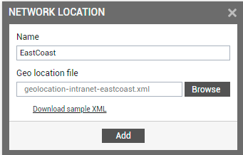
Now that the locations have been configured in the XML file, go back to Figure 6 Click the Browse button in Figure 6 to search for the XML file containing your location configurations. Once it is found, select it, so that your selection is reflected in the Geo location file text box, as depicted by Figure 7.
-
Finally, click the Add button in Figure 7 to add the new network location and upload the corresponding XML file to the eG manager. Figure 8 will then appear displaying the new location that you added.
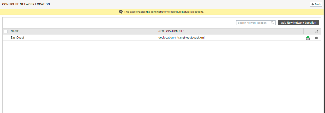
-
At any given point in time, you can make changes to the XML file mapped to a network location, save the updated file in a different name, and reupload the new file to the eG manager. For this, all you need to do is click on the
 icon corresponding to the network location displayed in Figure 8. Figure 9 will then appear, where you can specify the new XML file that should replace the old one.
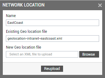
-
You can delete a location configuration, by clicking on the
 icon corresponding to it in Figure 8. Note that deleting a network location will not delete the XML file mapped to it.
Associating Network Locations with Infrastructure Elements
For the network locations and their configuration to take effect, you need to associate them with the eG Monitors that will need them for determining user locations. Currently, geo location discovery is only supported by the eG Real User Monitor (RUM), eG Citrix Virtual Apps/VDI Monitor, and the eG
If one/more of these eG Monitors are operational in your environment, then you need to associate the geo location mapper XML files created previously with those eG Monitors. Once this is done, then the eG Monitor to which the XML file is assigned will perform the following:
-
The eG Monitor will first check every incoming client IP for a match against the MaxMind database.
-
If a match is found, then the eG Monitor deems it to be a public IP address.
Note:
In Horizon/Citrix VDI environments, an incoming internet client's IP address may fail to find a match in MaxMind, if the correct client IP address is not registered with the Horizon Unified Access Gateway (UAG) / Citrix NetScaler that routes the connections. This is because one of the key pre-requisites for determining the geo location of internet users is to make sure that the correct client IP address is available with UAG/NetScaler.
-
If a matching IP address is not found in the MaxMind database, then the eG Monitor checks the private IP address ranges present in the geo location mapper XML file for a match. If a match is found, then the IP address is deemed to be a private IP address, and the location configuration defined for that IP address in the XML file is applied.
-
If the IP address does not find a match in the IP ranges (with or without subnet masks) configured in the XML file as well, then the eG Monitor will use the configuration defined within the 'default location' code block (step 7 in the previous section).
To assign the XML file to an eG Monitor, do the following:
-
Click on the Back button in Figure 8 to return to Figure 4. Then, click on the Assign Elements To Network Location button in Figure 4 to proceed. Figure 10 will then appear.
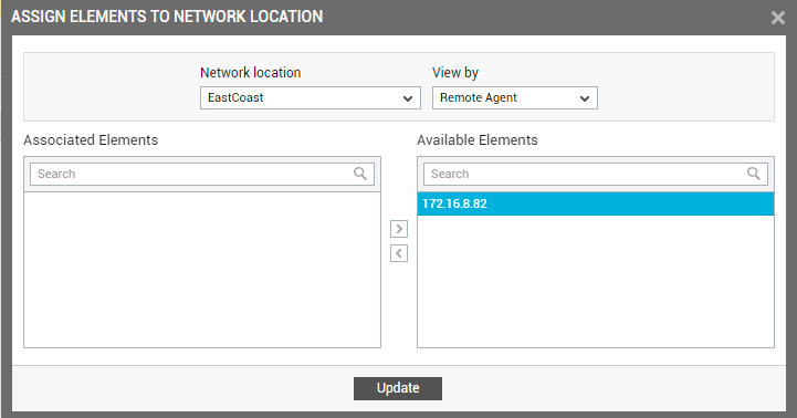
Figure 10 : Assigning the geo location mapper XML file to a remote agent
-
From Figure 8, first select the Network location that you want to assign. Then, pick a filter criteria from the View by drop-down. The options are as follows:
-
Remote agent: You can assign the XML file to the remote agent that monitors a Real User Monitor component, a Citrix Virtual Apps/VDI component, and/or a
-
Zone: You can assign the XML file to a zone containing one/more Real User Monitor components, Citrix Virtual Apps/VDI components, and/or
-
Segment: You can assign the XML file to a segment containing one/more Real User Monitor components, Citrix Virtual Apps/VDI components, and/or
-
Component:: You can assign the XML file to one/more Real User Monitor components, Citrix Virtual Apps/VDI components, and/or

Figure 11 : Selecting a component type to associate with the geo location mapper XML file
The Available Elements list will then be populated with all components of the chosen Component type.
-
-
From the Available Elements list, pick the elements you want to assign the XML file to, and click the < button. This will transfer the selection to the Associated Elements list.
-
Finally, click the Update button.
Troubleshooting Geo Location Mapping
Sometimes, in Horizon VDI environments, eG Enterprise may fail to determine the geography of Horizon VDI users who are connecting from the internet. This can happen if eG Enterprise is unable to discover the IP address of the client correctly.
This is typical in Horizon VDI environments, where users are not directly connecting to the Horizon Unified Access Gateway (UAG).
Generally, if internet users connect to the UAG directly, then the actual IP address of the user gets registered with the UAG. eG Enterprise will then be able to read the correct IP address from the UAG's registry and then use it to perform geo location determination.
In some environments however, a firewall with Network Address Translation (NAT) enabled, may be configured in the user-UAG path. This firewall will intercept incoming client connections, hide their actual IP address, and expose its NATed address to the UAG. Since the real client IP address is not available to eG Enterprise, it cannot perform geo location mapping properly.
In some other environments, a load balancer may front-end and route requests to a pair of UAGs. If that load balancer is not configured with the IP forwarding capability, it will only expose its internal IP address to the UAG instead of the actual client IP addresses. In this case again, geo location determination will fail.
Such geo location failures are also commonplace in environments where a NAT-enabled firewall / a load balancer without IP forwarding routes client connections to Citrix NetScaler.
For successful geo location discovery, it is important to ensure that the correct client IP address is always available to the UAG/NetScaler.
For this purpose, in environments such as the ones above, you need to do the following:
-
Disable NAT on the firewall that resides on the user - UAG/NetScaler path;
-
Configure the load balancer, so that it communicates the source IP address of the clients to the UAG/NetScaler. This can be achieved by using the X-Forwarded-For HTTP header field. This is a common method for identifying the originating IP address of a client connecting to a web server through an HTTP proxy or load balancer.