Tenant Management by Administrators
Every tenant who self-registers with eG Enterprise is allowed the freedom to manage their own infrastructure by downloading and installing agents, discovering and managing components, configuring tests and thresholds, and even grouping components to create business services and geographic zones. However, self-registered tenants cannot create personalized monitoring views for the other stakeholders in their enterprise using the eG Enterprise system. In short, a self-registered tenant cannot create additional tenants for the eG Enterprise system.
In this case therefore, a tenant has to approach the super user of the eG Enterprise system - i.e., the 'administrator' - for help in creating monitoring views for other users/groups in their enterprise.
Similarly, where tenant self-registration is disabled, only an administrator can create one/more tenants.
This topic provides the step-by-step procedure using which an administrator can create tenants. To this end, the topic takes an illustrated example. In this example, we will be creating a tenant account for a banking customer of an MSP. We will also be creating tenant accounts for the retail banking department of that bank and the user responsible for the performance of the mission-critical retail banking service offered by the bank.
The first step to creating a tenant is determining what entity type to assign to that tenant. eG Enterprise supports the following entity types:
-
Organization: An MSP for instance, can configure each of their customers as tenant Organizations in the eG Enterprise system. Likewise, a Cloud Service Provider can configure every cloud consumer as a tenant Organization. In the case of our example, we will be configuring a banking customer of an MSP as a tenant Organization.
- Organizational Unit: Smaller user groups within an organization can be created as Organizational units - eg., departments within an organization, support groups within a technical support cell, the different branches of an enterprise. In the case of our example, we will be configuring the Retail Banking department within the banking organization as an Organizational Unit. An Organizational Unit can contain more Organizational Units or individual Users.
-
User: These are individual users who can belong to an Organization or an Organizational Unit. In the case of our example, we will be configuring one member of the Retail Banking Organizational Unit of the banking Organization as a User.
Note:
Where tenant self-registration is enabled, every tenant who self-registers with the eG Enterprise system is by default registered as an Organization. This default setting can however be overridden. To achieve this, do the following:
- Edit the eg_ls_portal.ini file in the <EG_INSTALL_DIR>\manager\config directory (on Windows; on Unix, this will be the /opt/egurkha/manager/config directory).
- By default, the userModel parameter in the [LS_TRIAL_SETTINGS] section is set to Organization. If you want eG Enterprise to treat every tenant who self-registers as an Organizational Unit instead, then set userModel to Organizational Unit. On the other hand, if you want a self-registered tenant to be automatically assigned the User entity type, then set the userModel to User.
Let us now proceed to create a tenant of each entity type discussed above.
Creating an Organization
To achieve this, do the following:
- Login to the eG admin interface.
- Follow the User Management -> User -> Add menu sequence.
-
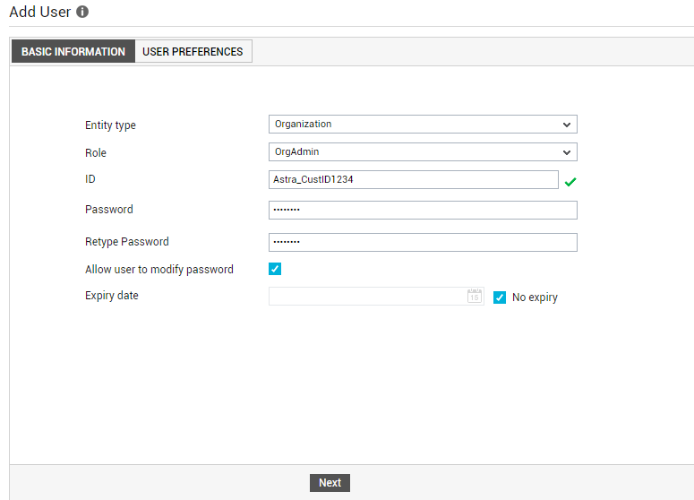
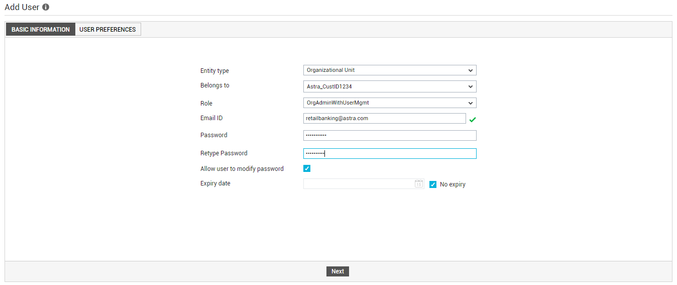
Figure 1 will then appear.
-
In Figure 1, first select Organization as the Entity type.
-
Next, assign a role to the new entity. You can choose from any of the default roles discussed below or create a new role and assign it to the entity:
-
OrgAdmin: This role allows an entity to administer and monitor a limited set of infrastructure elements alone. In other words, any entity who is assigned this role will be allowed access to the eG admin interface, so they can download and install agents for monitoring those components that have been explicitly assigned to them by the administrator, discover and manage such components, and configure tests, thresholds, and alarm policies for these components. The role also enables the entity to build new segments, services, groups, and zones for monitoring using the assigned components. The entity can also login to the eG monitoring console to understand the performance and problems pertaining to the components, services, segments, and zones that are part of their specific monitoring scope. The role also allows the entity access to the Configuration Management interface, but does not authorize them to create, modify, or delete additional users/entities/roles.
Note:
Self-registered tenants are automatically assigned the OrgAdmin role.
- OrgAdminNoConfig: This role enables an entity to perform all activities that an OrgAdmin can, but does not allow the entity access to the Configuration Management interface.
- OrgAdminWithUserMgmt: In addition to OrgAdmin privileges, this role also enables the entity to perform user management by adding, modifying, and deleting users/roles/entities.
- OrgAdminWithUserMgmtNoConfig: An entity who is assigned this role is allowed all privileges of an OrgAdminWithUserMgmt, except the right to access the Configuration Management interface.
- Monitor: This role can only be assigned to the Entity type, User. If the eG license enables the eG Reporter and Configuration Management capabilities, then Monitor users will have access to the monitoring, reporting, and configuration management consoles of eG Enterprise. In these consoles, the monitor user can view the details pertaining to only those components/segments/services/zones/service groups that have been explicitly assigned to him/her. Each monitor user is associated with an email address to which alarms pertaining to the assigned elements will be forwarded. The user’s profile also includes information regarding his/her alarm preferences - whether alarms have to be forwarded in text or HTML mode, whether a complete list of alarms has to be generated each time a new alarm is added, or whether the new alarm alone should be sent via email, etc. Each monitor user is associated with a subscription period. eG Enterprise allows the monitor users to access the system until this period only.
-
AlarmViewer: This role can only be assigned to the Entity type, User. This role is ideal for help desk personnel. The users vested with AlarmViewer permissions can login to the monitor interface, and perform the following functions:
- View the details of alarms associated with the specific components and services assigned to them
- Provide feedback on fixes for the alarms
-
View feedback history
Like Monitor users, users with this role can only monitor the components assigned to them.
- MonitorNoConfig: This role can only be assigned to the Entity type, User. The users who have been assigned the MonitorNoConfig role will have access to the eG monitoring and reporting interfaces only, and not the eG Configuration Management interface.
- MonitorWithLimitedAdmin: This role can only be assigned to the Entity type, User. Administrators can create additional users with administrative privileges to configure the monitoring for the components that are assigned to them. These users can configure tests, thresholds, alarm policies and maintenance policies for the components in their purview. The MonitorWithLimitedAdmin role included in eG Enterprise can be used to create such users. This capability allows delegated administration, which is a key requirement for many enterprises and service providers.
- MonitorWithLimitedAdminNoConfig: This role can only be assigned to the Entity type, User. This role can only be assigned to the Entity type, User. Users with MonitorwithLimitedAdminNoConfig privileges will have unrestricted access to the components assigned to them. This includes administrative access to configure tests, thresholds, alarm policies and maintenance policies for the components assigned to them. Though these users are provided with access to monitoring and reporting consoles, they are denied access to configuration management console, even if the eG license enables this capability.
-
- When creating an Organization, you will have to provide a unique ID for the organization. The tenant Organization will be registered using this ID. For logging into the eG web console, the Organization should use this ID only.
- Next, specify the Password to be used at login. Confirm the password by re-entering it in the Retype Password text box.
- By default, any tenant can edit their profile in the eG Enterprise system to modify their password. If you do not want tenants to modify their passwords, then deselect the Allow user to modify password check box.
- A tenant account registered with the eG Enterprise system will be valid only until the date specified against the Expiry date text box. Beyond this date, the account will automatically become inactive. You can choose not to specify an expiry date for a tenant, if you so wish. For this, select the No expiry check box. If this is done, then the tenant account will remain active for an indefinite period of time.
-
Then, click the Next button.Figure 2 will then appear.
-
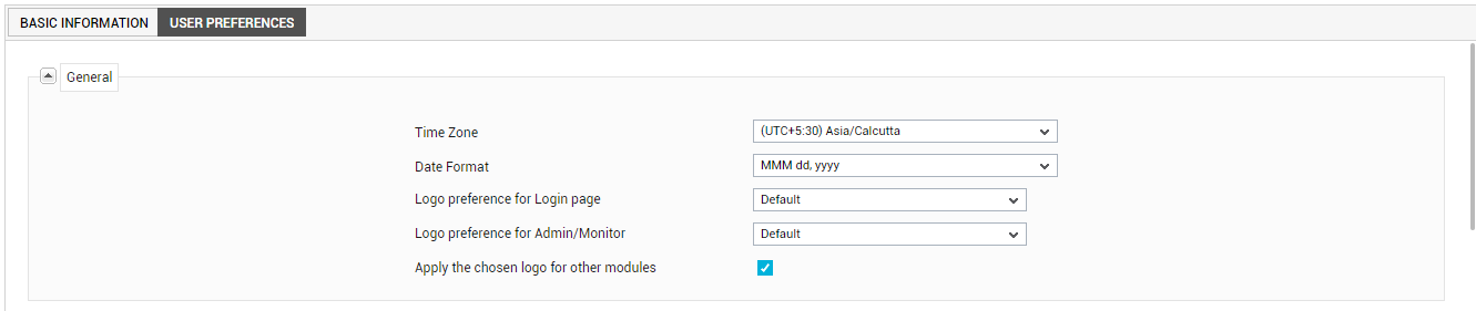
In the General section of Figure 2, specify the following:
-
Time Zone: eG Enterprise is often deployed to manage servers in different geographies and time zones. For example, a large enterprise may have a central eG Enterprise management console to which agents from different locations can be reporting. In a managed service provider environment, multiple customer infrastructures can be monitored from the same eG manager. In such situations, tenants (administrators in different geographies, customers of an MSP in different regions) prefer to see the performance metrics reported in their respective time zones. eG Enterprise allows time zones to be associated to each tenant. By default, all tenants are associated with the local time zone of the location where the eG manager is hosted. However, an administrator can change the time zone preferences of a tenant to suit that tenant’s requirements. For this, when creating a profile of a tenant, the administrator can pick a Time zone for that tenant. When that tenant logs into the eG Enterprise console, all the metrics, alerts, and reports that the tenant accesses will be displayed in the respective local time zone. This capability ensures that eG Enterprise tenants receive a completely ‘local’ experience, regardless of which part of the world the eG manager is located in.
To understand time zone association better, take the case of an example. Assume that a tenant Organization, which has received the email depicted by Figure 3, has been configured to use the time zone, Asia/Calcutta. We can thus conclude that the Start Time of the problem indicated by Figure 3 has been determined based on the time settings of the Asia/Calcutta zone.
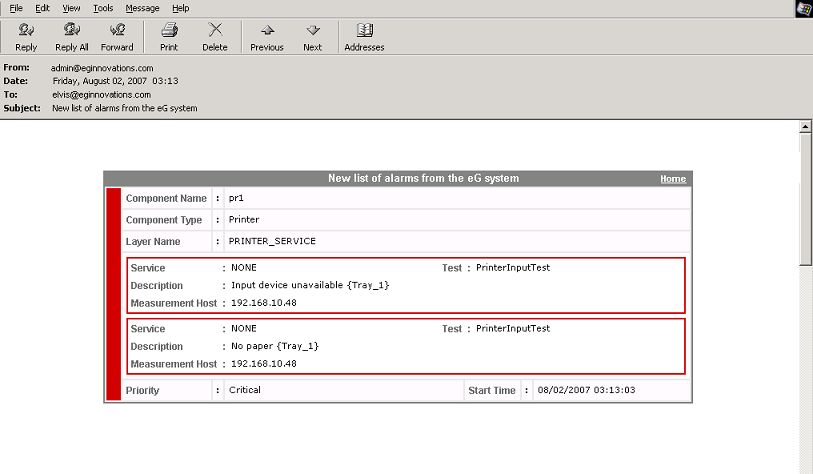
Figure 3 : Email alert of tenant elvis
Now, assume that another Organization has been configured to receive email notification of the same problem. However, this Organization has been assigned the Asia/Singapore time zone. Figure 4 depicts the email alert of this Organization.
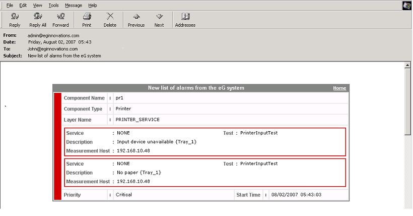
Figure 4 : Email alert for tenant john
In Figure 4, you can see that while the other problem details remain the same as in Figure 4, the Start Time has changed to reflect the time settings of the Asia/Singapore zone.
Note:
While configuring a time zone, remember the following:
- When normal mails are generated by the eG manager, the Start Time displayed in such mails will also be based on the time zone setting for the corresponding tenant.
- If a tenant is configured to use multiple email IDs (i.e., a comma-separated list of mail IDs has been provided in the To, cc, and/or bcc columns), then the time zone specification for that tenant applies to all the configured email IDs. In other words, every tenant can have a separate time zone, but every mail ID configured for a tenant cannot have a separate time zone.
- When mail alerts are being escalated, the time zone settings will be derived from the tenant account that the alarms pertain to. In other words, each escalation level will NOT have a separate time zone - the time zone setting for the tenant account will apply to escalated mails as well.
-
Any alerts generated by the eG manager to report an unusual situation with the eG manager itself (e.g., database not working, agent not running, etc.) will not be affected by this time zone settings. All such alerts will be generated in the eG manager’s local time zone setting.
- Date format: The default date format for the eG user interface is MMM dd, yyyy. This date format can be changed depending upon the country in which the tenant being created lives, by selecting a different format from the Date format list. Whenever this tenant logs in, the eG user interface will display dates in the chosen format only. This is particularly useful in MSP environments, where customers of the MSP could be separated by geographies and may require performance and problem reports of their hosted enivonments to be delivered in the date format that applies to their geography.
-
Logo preference for Login page, Logo preferences for Admin/Monitor module, and Apply the chosen logo for other modules: Typically, using the Logo/Messages menu option in the Settings tile, an administrator can configure a custom logo for the login screen and for every module that is enabled in the eG license – i.e., the Admin, Monitor, eG Reporter, and/or the eG Configuration Management module. MSP environments typically create a tenant profile in eG for each customer environment they host. While administrative rights to the eG Enterprise system will generally lie with the MSP, the customers may be granted access to one/more of the other consoles. Each of these customers may want to have their company’s logo appear when they login into a console, as opposed to the MSP’s logo. The General section of the user preferences tab page enables the configuration of tenant-specific logos – one for every tenant registered with the eG Enterprise system – so that MSP customers see their company logo in the modules they have access to.
By default, the Default logo will be assigned to the login page and the Admin/Monitor modules. The Defaultlogo is the logo configured for the login page and for the Admin/Monitor using theLogo/Messages option in the settings panel of the monitor settings page. To define a custom logo for a tenant, select the Custom option against the module for which you want to set the custom logo. Then, click the button adjacent to the list box to upload the custom logo to the eG manager. Figure 5 will then appear.
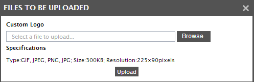
Figure 5 : Uploading the logo to the eG manager
The type, size and resolution of the logo image should match with the specifications mentioned in Figure 5. Click the Browse button in Figure 5to browse for the custom logo image, and then click the Upload button to upload the image. When the tenant logs into a specific module of the manager, the logo customized for that tenant for that module will get displayed.
If the logo chosen for the Admin/Monitor module has to be applied to all the other modules of the eG management console (i.e., the eG Reporter and Configuration Management modules), then select the Apply the chosen logo for other modules check box in Figure 2.
-
-
In the Mail/SMS Settings section of Figure 6, specify the following:
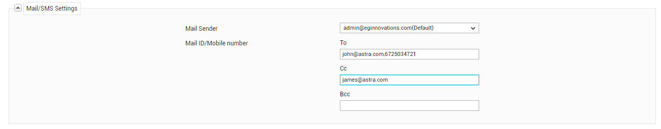
Figure 6 : Configuring Mail/SMS Settings
- Mail Sender: This option appears if at least one alarm priority is chosen from the ‘Alarms by mail / SMS’ section. By default, eG Enterprise sends email alerts from the eG Administrator Mail ID configured in the mail server SETTINGS page in the eG administrative interface. In MSP environments typically, different support groups are created to address performance issues relating to different customers. These support groups might prefer to receive problem intimation from customer-specific mail IDs instead of the global admin mail ID, so that they can instantly identify the customer environment that is experiencing problems currently. Moreover, this way, every support group will be enabled to send status updates on reported issues directly to the concerned customer, instead of overloading the admin mailbox. To facilitate this, the mail server settings page allows the administrator to configure multiple Alternative mail sender IDs - normally, one each for every customer in case of an MSP environment. Moreover, while creating a new tenant, the administrator can select one of these configured sender IDs from the Mail Sender list and assign it to the new tenant, so that all email alerts received by the tenant are generated by the chosen ID only. Moreover, the EG Administrator Mail IDspecified in the MAIL/SMS SETTINGS page will also be added to the Mail Sender list in this page, and will be the default selection.
-
Mail ID/Mobile number: This option will appear only if at least one check box is selected from the ‘Alarms by mail / SMS’ section. The Mail ID/Mobile numberoption allows a mail account(s) / mobile number(s) to be associated with a tenant. When multiple mail IDs are specified, an administrator can specify which mail address(es) need to be in the To: field of the mail alarm and which ones should be in the Cc: and Bcc: fields. In the same way, you can even provide mobile numbers in the To:, Cc:,and Bcc:fields.
If a mobile number(s) is specified then a compact alarm report that is ideal for a mobile phone console is generated. The first line of this report comprises of the following information, separated by slash (/).
- IP address and port of the problem component
- The component type
The second line of this report would consist of the following information (separated by slash):
- The name of the test that generated the problem measure(s)
- The name of the problematic measure
- The name of the service; this would be NONE if the problem component does not host any service
Given below is a sample report transmitted via SMS:
192.168.10.8:7077/Web_server
ProcessTest/Num_procs_running/HTTPD/NONE
In the above example:
192.168.10.8:7077, represents the IP address and port of the component which has encountered a problem
Web_server is the type of component
ProcessTest is the name of the test that generated the problem measures
Num_procs_running is the name of the problematic measure
HTTPD is the name of the descriptor
NONE denotes that the web server does not host any service
Note:
eG alarms will be forwarded to a mobile phone only if the NowSMS Lite SMS manager or the eG SMS Manager has been installed in the network, and the eG manager has been configured to work with the SMS manager.
-
In the Alert Settings section of Figure 7, specify the following:
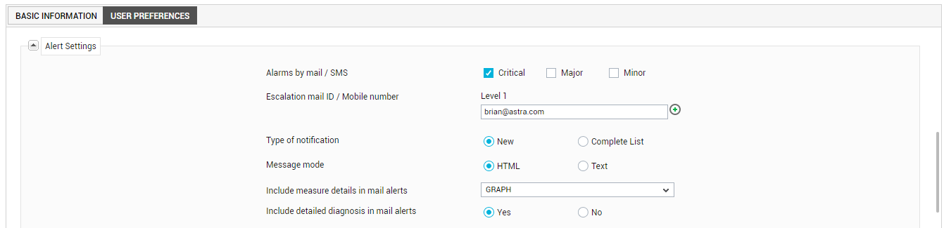
Figure 7 : Configuring Alert Settings
- Alarms by mail / SMS: The eG manager is capable of alerting tenants as and when problems occur. The alarms are classified into critical, major, and minor. By choosing one or more of the check boxes corresponding to the Alarms by mail /SMS field, a tenant can indicate his/her preference in terms of the priority of problems for which he/she wishes critical priority alarms alone and not the other types. If no alarm priority is chosen, then the tenant will not receive alerts by email / SMS.
-
Escalation mail ID / mobile number: To ensure the continuous availability of mission-critical IT services, it is essential that problems be detected at the earliest and remedial action be initiated immediately. Naturally, the performance of an IT operations team is assessed by its ability to proactively isolate problems and by the speed with which the identified issues are fixed. As most IT operations teams are required to support strict service level guarantees, problems that remain unnoticed or unresolved for long periods of time could result in service level violations, warrant severe penalties, and ultimately even impact the reputation of the service provider.
The eG Enterprise, with its patented correlation technology and its multi-modal (email/SMS/pager/console) problem alerting capability accurately identifies potential issues in the monitored environment, and intimates the concerned IT operators before any irredeemable damage is done. To enable IT managers to proactively track the performance of their operations teams, eG Enterprise also includes a time-based alarm escalation capability. With this capability, when a problem remains unresolved for a long time period, the eG Enterprise manager automatically escalates the alarm to one or more levels of IT managers. The alarm escalation is based on a pre-defined escalation period, which is configured by the administrator of eG Enterprise.
The escalations are personalized for each tenant - i.e., each tenant in the eG Enterprise system is associated with multiple levels of managers. When an alert that has been sent to a tenant is not resolved within the escalation period, the alert is forwarded to the first level of management. If the problem remains unresolved for another escalation period, the second level of management is informed, and so on. By hierarchically escalating problems to IT managers, eG Enterprise ensures that the management staff stays informed of the state of the mission-critical IT services they control, and that they can intervene in a timely manner to ensure quick and effective resolution to key problems.
The Escalation mail ID section of Figure 7 is where the different levels of escalation need to be specified. A comma-separated list of mail IDs/mobile numbers can be specified for the Level 1field to indicate the first level of escalation. You can, if you so desire, define additional support levels by clicking on the '+' sign that appears at the end of the Level 1text box. This way, issues that remain unresolved even at Level 1will be escalated to Level 2and so on. You can create up to a maximum of 5 escalation levels. To delete a newly added level, click on the '-' sign at the end of the corresponding Leveltext box.
Note:
Alarm escalation will work only if you configure the following:
- The duration beyond which the eG Enterprise system needs to escalate a problem to the next level
- The alarm priorities to be escalated
Both these parameters can be configured using the alarm escalation section in the mail alert preferences page that appears when the Alert Settings option is selected from the Mail Settings menu of the Alerts tile.
Note:
By default, where multiple levels of escalation are configured, the eG manager does not consider the changes that may occur in the priority of an alarm between two levels of escalation. For instance, if the priority of an alarm changes from Major to Critical after the first level escalation alert is sent, the second level escalation alert will be sent for the Critical alarm only. Recipients of the second level escalation alerts will hence have no knowledge of the original state of that alarm. Similarly, recipients of the first level escalation alerts will not know that the alarm priority has changed. In the absence of complete problem information, the recipients of escalation alerts may not be able to perform effective problem diagnosis and provide accurate solutions. To avoid this, you can now configure the eG manager to reset escalation levels if a state transition occurs. This way, if the alarm priority changes after the first level escalation, the escalation cycle will begin all over again – i.e., escalation alerts related to the modified alarm will first be sent to the first level recipients and then the next level and so on.
- Type of notification: By choosing the New option, an administrator can indicate to eG Enterprise that when alerting a tenant via email/SMS, the system should send the details of newly added alarms only. On the other hand, if the Complete option is chosen, the tenant will receive a complete list of current alarms every time a mail/SMS message is generated.
-
Message mode: This option governs the format in which an alarm is reported in an email message. If the HTML option is chosen, the alarm details are formatted as HTML text whereas the Text option formats the alarm details as plain text.
Note:
If HTML is chosen as the Message mode, then alarms sent by mail will carry a hyperlink named home at the right top corner. The destination of the hyperlink can be configured using the eg_services.ini file in the <EG_INSTALL_DIR>\manager\config directory. The [MISC_ARGS] section of the eg_services.ini file contains a MailHomeURL parameter that is left blank by default. In this case, clicking on the home link will connect you to the eG manager and open the login screen. By providing a specific URL against MailHomeURL, you can ensure that tenants are lead to the specified URL upon clicking the home hyperlink.
- Include measure details in mail alerts: By default, the No option is chosen from the Include measure details in mail alerts list, indicating that the email alerts to a tenant will not include any measure details. However, if you want the email alerts to a tenant to include a time-of-day graph of the problem measure plotted for the last 1 hour (by default), then, pick the Graph option from this list. If you want the email alerts to a tenant to include the data plotted in a 1-hour measure graph, then, pick the Data option from this list.
- Include detailed diagnosis in mail alerts: By default, this flag is set to No. This implies that, by default, the detailed diagnosis (if available) of the problem measure will not be sent along with the email alerts to tenants. If you want the email alerts to a specific tenant to include detailed diagnosis information as well, then, set the Include detailed diagnosis in mail alertsflag to Yes. This information will enable tenants to move closer to the root-cause of the problem condition.
-
Email alerts only during shift periods: Some environments - especially the ones that span geographies - could have operators working in shifts; for instance, an MSP environment could comprise of one/more support groups, which might work only in the nights, in order to provide help-desk services to the customers in a particular geographic region. The user in these groups naturally, would want to receive email alerts of issues only during their working hours; during the rest of day, they may prefer to be alerted via SMS. To facilitate this, eG Enterprise allows you to configure shift periods for individual tenants. Separate shift periods can be configured for receiving email alerts, SMS alerts, and escalation mails.
For instance, if you want to indicate on which days and at what times a tenant needs to receive email alerts of issues, then you should first enable the Email alerts only during shift periods flag, by setting it to Yes.
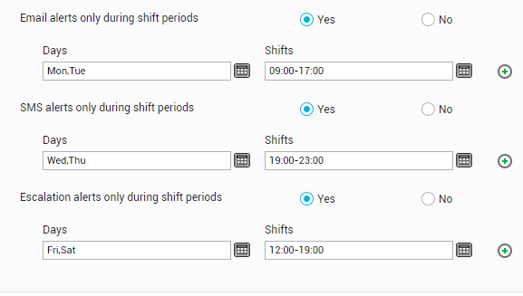
Figure 8 : Configuring email/SMS/escalation shift periods
Note:
In environments where shifts are not relevant, the Email alerts only during shift periods flag may be meaningless. You can therefore ensure that this flag does not appear in the user preferences tab page by following the steps given below:
- Select the Alert Settings option from the Mail Alerts menu of the Alerts tile.
- Select the Shift Periods node from the Settings tree in the left panel of the page that appears.
- When the shift periods configuration section appears in the right panel, set the Allow shift period configuration flag to No. By default, this flag is set to Yes.
- Finally, register the changes by clicking the Update button in that page.
Upon setting the flag toYes, you will be required to specify the Days on which the user should receive email alerts; also, in the Shifts field alongside, you need to mention the specific time periods on the chosen Days at which the user should receive email alerts (see Figure 8).
To select one/more Days, do the following:
- First, click on the Calendar control (
 ) next to the Days field.
 From the days list that pops out (see Figure 9), which lists the days of the week, select the days on which email alerts need to be sent to the user.
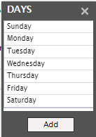
- To choose more than one day from the list, select a day by clicking on the left mouse button, and then, with the Ctrl button on your keyboard pressed, click on another day to select it. Similarly, multiple days can be selected. To add your selection to the Days field, click the Add button in the days list. You will thus return to the user preferences tab page where the selected days will be listed against the Days field (see Figure 8).
Next, using the Shifts field, provide the specific time periods at which email alerts should be sent out to the user on the chosen days. For that, do the following:
-
First, click on the Calendar control (
) next to the Shifts field. Doing so invokes the shifts window, wherein you can specify a From time and To time for your shift (see Figure 10). Ensure that the shift timings correspond to the Time zone chosen for the user. 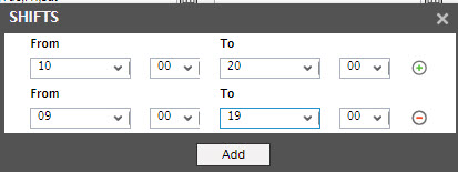
- To provide an additional time slot, click on the circled ‘+’ button at the end of the first row. Another row then comes up wherein you can provide one more time period (see Figure 10). In this way, you can associate a maximum of 5 shift periods with the chosen Days.
- To remove a shift period from the shifts window, simply click on the circled ‘-‘ button against the corresponding specification. Finally, to add these time periods to the Shifts field, click on the Add button in the shifts window. You will thus return to the user preferences tabpage, where you can find the time period(s) that you specified appear against the Shifts field (see Figure 8 ).
With that, one Day-Shift specification is complete.
To add another Day-Shift specification, just click on the circled ‘+’ button at the end of the first row . Another row will then appear, where you can specify a few more Days and Shifts. This way, a number of Day-Shift specifications can be associated with a user ( Figure 11).
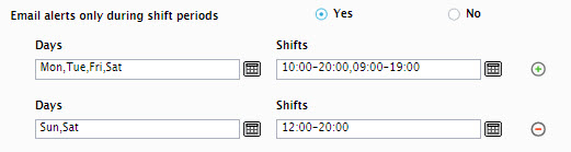
Figure 11 : Configuring multiple Day-Shift combinations
This number is configurable, and can be any number between or equal to 1 and 10. To configure this number, go to the shift periods configuration section of the mail alert preferencespage that appears when you click on the Alert Settings option of the Mail Settings menu in the Alerts tile. In the shift period configuration section, select the Maximum number of day-shift combinations.
To delete a particular Day-Shift specification from Figure 11, simply click on the circled ‘-‘ button in Figure 11.
-
SMS alerts only during shift periods: Similar to email alerts, SMS alerts can also be configured to be sent out only during specified time periods on specific days of the week. The first step towards this is to enable the SMS alerts only during shift periods flag by selecting the Yes option in the user preferences tab page. Using the Days and Shifts fields that appear subsequently, you can configure one/more Day-Shift combinations in the same manner as discussed for email alerts.
Note:
In environments where shifts are not relevant, the SMS alerts only during shift periods flag is meaningless. You can therefore ensure that this flag does not appear in the user preferences page by following the steps given below:
- Select the Alert Settings option from the Mail Alerts menu of the Alerts tile.
- Select the Shift Periods node from the Settings tree in the left panel of the page that appears.
- When the shift periods configuration section appears in the right panel, set the Allow shift period configuration flag to No. By default, this flag is set to Yes.
- Finally, register the changes by clicking the Update button in that page.
-
Escalation alerts only during shift periods: Like email and SMS alerts, the eG manager can be configured to send escalation mails/SMS’ also at pre-defined days and time slots. To enable this capability, first, turn on the Escalation alerts only during shift periods flag by selecting the Yes option in the user preferencespage. As before, this will bring up the Days and Shifts fields , using which you can configure the days on which and the times at which alerts are to be escalated to the specified individuals. The procedure for configuring the Day-Shift combinations is the same as that for email and SMS alerts.
Note:
In environments where shifts are not relevant, the Escalation alerts only during shift periods flag is meaningless. You can therefore ensure that this flag does not appear in the user preferences page by following the steps given below:
- Select the Alert Settings option from the Mail Alerts menu of the Alerts tile.
- Select the Shift Periods node from the Settings tree in the left panel of the page that appears.
- When the shift periods configuration section appears in the right panel, set the Allow shift period configuration flag to No. By default, this flag is set to Yes.
-
Finally, register the changes by clicking the Update button in that page.
-
Next, in the Monitor section, you can configure the settings depicted by Figure 12:
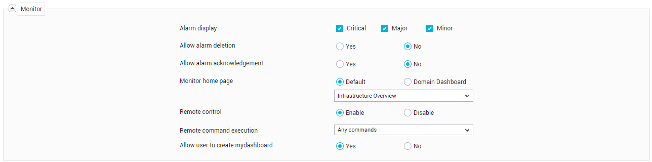
Figure 12 : Configuring Monitor Settings
- Alarm display: By selecting one or more options provided against this field, you can associate specific alarm priorities with the tenant being created. When this tenant later logs into the eG monitor interface, alarms of the chosen priorities alone will be displayed in the current alarmswindow of the eG monitor interface.
- Allow alarm deletion: To allow the new tenant to delete alarms from the CURRENT ALARMS window in the eG monitor interface, select the Yes option from the Allow alarm deletion section.
-
Allow alarm acknowledgement: Optionally, specific tenants can be configured to acknowledge an alarm displayed in the eG monitor interface. By acknowledging an alarm, a tenant can indicate to other tenants that the issue raised by an alarm is being attended to. In fact, if need be, the tenant can even propose a course of action using this interface. In such a case, a tenant with Admin or Supermonitor privileges (roles) can edit the acknowledgement by providing their own comments/suggestions on the proposed action. The acknowledgement thus works in three ways:
- Ensures that multiple members of the administrative staff do not unnecessarily invest their time and effort in resolving a single issue;
- Serves as a healthy forum for discussing and identifying permanent cures for persistent performance ills;
- Indicates to other tenants the status of an alarm
To enable the alarm acknowledgement capability for the new tenant, select the Yes option from the Allow alarm acknowledgement section in Figure 12.
-
Monitor Home Page: By default, the MonitorDashboard appears as the home page of the eG monitoring console - i.e., as soon as a user logs into the monitoring console, the Monitor Dashboard appears as the first page by default. eG Enterprise however, allows administrators to set any page they deem fit as the Monitor Home Page for individual tenants to the eG monitoring console. This way, every tenant, upon logging into the eG monitor interface, is enabled to view straight up the information that interests them the most, thereby saving time and minimizing the mouse clicks that may be required to navigate to that information!
-
Remote control: Using this option, you can indicate whether the new tenant is to be provided access to the managed components. This capability, when enabled, allows tenants to remotely manage and control components from a web browser itself. By default, this capability will be Disabled for a new tenant. To enable this capability for a particular tenant, select the Enable option. Doing so invokes a Remote command execution list (see Figure 12), using which you need to indicate whether the new tenant is authorized to execute any command remotely, or is only allowed to choose from a pre-configured list of commands.
- Allow user to create mydashboard: With eG Enterprise, tenants have the option to build a customizable MyDashboard, using which they can graphically compare current and historical performance of multiple applications of interest to them. This dashboard not only allows a tenant to choose the components to focus on, but also pick the measures and even descriptors that should be featured in it. By default, this dashboard capability is enabled for any new tenant. Accordingly, the Allow user to create mydashboard flag is set to Yes by default. If you want to disable this capability for any tenant, set this flag to No.
-
In the Reporter section, specify the following (see Figure 13):
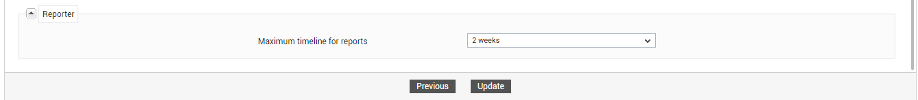
Figure 13 : Configuring Reporter settings
-
Maximum timeline for reports: Typically, eG Enterprise permits multiple tenants to simultaneously access the eG Reporter console and generate a wide variety of reports spanning any timeline of their choice. While this imparted tremendous flexibility in report generation, when tenants logged in concurrently and generated multiple reports across broad time periods, report generation could slow down a little. In order to avoid this, administrators can set the maximum timeline for which each tenant can generate reports, by selecting an option from the Maximum timeline for reportslist in Figure 13. By default, 2 weeks will be selected here. This implies that the user being created can generate reports for a maximum timeline of 2 weeks only, by default. You can override this default settings by picking any other timeline from this list. If you do not want to impose any timeline restriction on a tenant, then you can set the Maximum timeline for reports to Unlimited. This enables the tenant to generate reports for any timeline.
-
-
Then, click the Update button in Figure 13 to save your configurations in the User Preferences tab page.
Note:
At any given point in time, you can close any section that is available for configuration in the user preferences tab page by clicking the down arrow button that precedes the section name. For instance, the Reporter section can be closed by clicking the ‘down-arrow’ button adjacent to the section name, Reporter.
-
Updating user preferences invokes the Elements Association tab page.
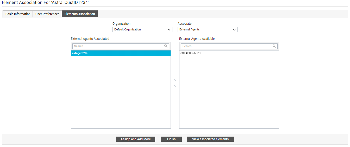
Figure 14 : Associating infrastructure elements with a tenant Organization
-
Using Figure 14, you can associate one/more infrastructure elements such as zones/services/segments/components with the new tenant. Additionally, external agents and remote agents can also be associated with a new tenant. With the banking Organization in our example, let us associate all external and remote agents configured for the bank. For that, do the following:
- First, select the Organization from which the elements are to be chosen for association. By default, all managed infrastructure elements are mapped to the Default Organization. When creating a new tenant Organization therefore, you will have to pick elements from the Default Organization and assign them to the new tenant Organization. This is why, more often than not, you will be selecting the Default Organization option from the Organization drop-down in Figure 14. However, sometimes, the elements of interest to you may have already been assigned to another Organization, and not the Default Organization. If you want to associate such elements with the new tenant Organization, then first select the parent Organization from the Organization drop-down.
-
Next, from the Associate drop-down, pick the type of element that you want to assign to the new tenant. Your options are as follows: Components, Segments, Services, Service Groups, Zones, External Agents, Remote Agents, and Virtual Machines. To assign external agents, pick the External Agents option. The available external agents will then be listed in the External Agents Available list. From this list, select the external agents that the banking environment should use and click the < button. This will transfer your selection to the External Agents Associated list (see Figure 15).
Figure 15 : Associating external agents with the tenant Organization
-
With that, external agents are associated with the banking Organization. Next, proceed to assign remote agents. For that, first click the Assign and Add More button in Figure 15. Then, pick the Remote Agents option from the Associate list, select the remote agent you want to assign from the Remote Agents Available list, and click the < button. Your selection will be transferred to the Remote Agents Assigned list (see Figure 16). This means that the banking tenant in our example can now use the chosen remote agents to monitor any component assigned to them.
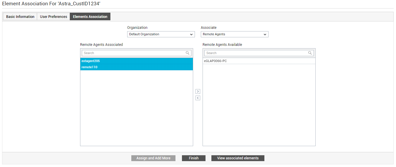
Figure 16 : Associating one/more remote agents with the tenant Organization
-
Next, let us see how we can add zones to the tenant Organization. For that, click the Assign and Add More button in Figure 16, and then select the Zones option from the Associate list. The Zones Available list will then be populated with the pre-configured zones.
Whenever a tenant Organization self-registers with the eG Enterprise system or is manually added to the system by an administrator, a zone named after that Organization is automatically created in the system. However, this zone will not be automatically assigned to the Organization in question. To associate this zone with the Organization, select the zone that has the same name as the Organization from the Zones Available list and click the < button (see Figure 17).
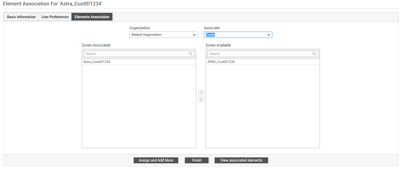
Figure 17 : Associating the auto-created zone with the corresponding tenant Organization
Also, this zone will be empty. Every time an independent component is assigned to a tenant Organization, that component will be automatically added to the zone that corresponds to it. So, let us now proceed to assign an independent component to the Organization in our example.
-
To map an independent component with a tenant Organization, first click the Assign and Add More button in Figure 18. Then, select the Components option from the Associate list. A Component type drop-down will then appear. Select the type of component you want to assign from this list. All independent components of the chosen type will then appear in the Components Available list. From this list, select the component that you want to assign to the Organization and click the < button.
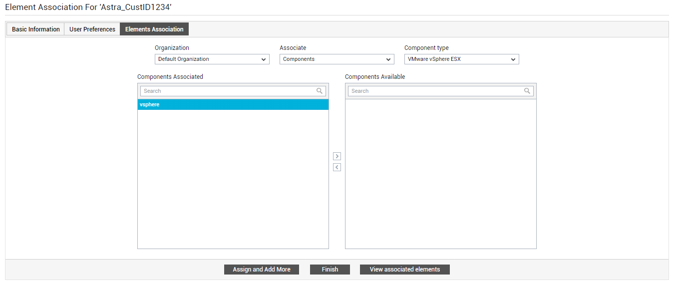
Figure 18 : Assigning independent components to the Organization
-
Fully-configured business services in the eG Enterprise system can also be assigned to a tenant. Say that a retail banking service is operating in the banking environment in our example. To assign this service to the tenant Organization in our example, first click the Assign and Add More button in Figure 18. Then, select the Services option from the Associate drop-down, pick the retail banking service from the Services Available list, and click the < button. Note that when you associate a service with a tenant, all components engaged in the delivery of that service are automatically assigned to that tenant.
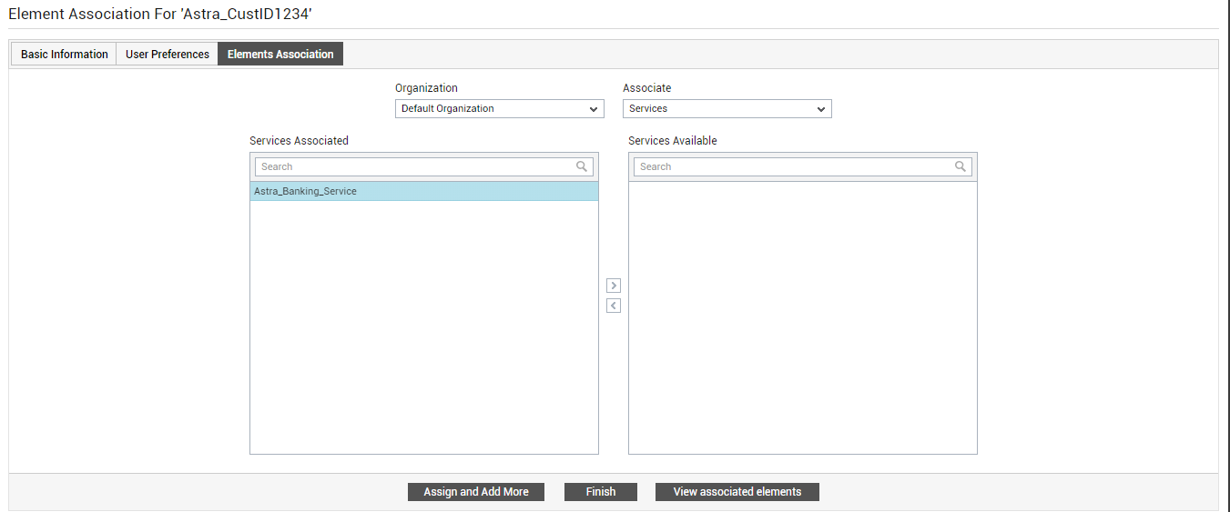
Figure 19 : Associating a business service with the tenant Organization
- Likewise, you can assign segments to a tenant. This is useful if the tenant environment comprises of groups of inter-related components, where a problem in one component can ripple and affect the performance of another. Similarly, virtual machines can also be assigned to specific tenants. This feature is particularly useful for cloud service providers, who often need to provision a VM on-demand for any customer who requests for it. These cloud consumers (i.e., customers) are only concerned with the availability and internal health of those VMs that the service provider has provisioned for them, as typically, they will have no knowledge of the virtual servers on which the VMs operate. This means that these customers may not require monitoring access to the whole virtual server as such. Such customers can be configured as tenant Organizations in the eG Enterprise system. In the process, the administrator can configure tenant-VM mappings using the eG administrative interface. With the help of these mappings, the cloud service providers will not only be able to track who is using which VM, but will also be able to provide a customer (i.e., tenant, in eG parlance).
-
For the purpose of our example however, we will not be assigning virtual machines and segments. The next step therefore is to review the element associations configured thus far, and save them if they are in order. Click the View associated elements button in Figure 19 to check your element associations. Figure 20 will then appear.
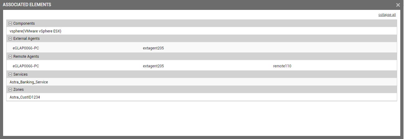
- Once you are satisfied with your specifications, close the window depicted by Figure 20 and click the Finish button in Figure 19.
Creating an Organizational Unit
Now that an Organization has been created, let us proceed to create an Organizational Unit within that organization. For our example, we will be configuring the Retail Banking department of the banking Organization as an Organizational Unit. Since this department is responsible for maintaining the retail banking service in our example, we will be assigning this service to this organizational unit. The steps for achieving this are as follows:
- Login to the eG admin interface.
- Follow the User Management -> User -> Add menu sequence.
-
Figure 21 will then appear.
- In Figure 21, first select Organizational Unit as the Entity type.
- Then, from the Belongs to drop-down, select the Organization to which the Organizational Unit you are creating belongs. In the case of our example, select the Organization you created in the Creating an Organization section.
- Next, assign a Role to the new entity. You can choose from any of the default roles discussed at step 5 of Creating an Organization, or create a new role and assign it to the entity.
-
Now, provide a valid Email ID to the tenant Organization Unit. The Organizational Unit will be registered using this email ID. For logging into the eG web console, the Organizational Unit should use this email ID only.
- Next, specify the Password to be used at login. Confirm the password by re-entering it in the Retype Password text box.
- By default, any tenant can edit their profile in the eG Enterprise system to modify their password. If you do not want tenants to modify their passwords, then deselect the Allow user to modify password check box.
- A tenant account registered with the eG Enterprise system will be valid only until the date specified against the Expiry date text box. Beyond this date, the account will automatically become inactive. You can choose not to specify an expiry date for a tenant, if you so wish. For this, select the No expiry check box. If this is done, then the tenant account will remain active for an indefinite period of time.
- Then, click the Next button, and follow the steps 11-16 in Creating an Organization to define the access privileges and alerting preferences for the Organizational Unit.
-
When the ELEMENT ASSOCIATION page appears, proceed to associate the retail banking service to the Organizational Unit. For that, select Services from the Associate drop-down, select the retail banking service from the Services Available list and click the < button. Finally, click the Finish button to save the specifications.
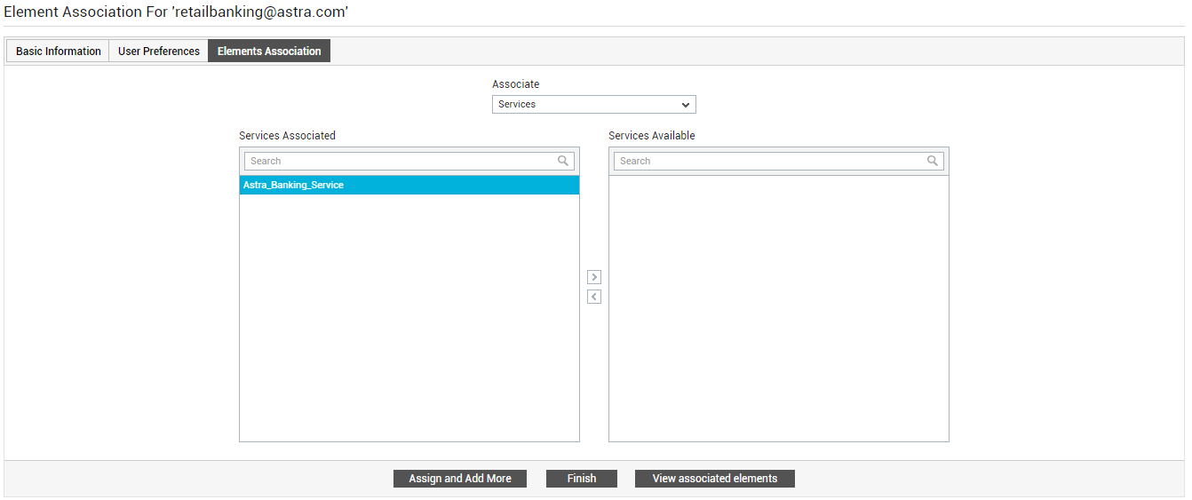
Figure 22 : Assigning the retail banking service to the Organizational Unit in our example
Creating a User
Let us now proceed to create a tenant account for a database administrator, john, who is responsible for attending to issues with the Microsoft SQL database server engaged in the delivery of the retail banking service. This user would need to receive real-time updates on the performance and problems related to the Microsoft SQL database server. This way, he can promptly detect database server issues and resolve them rapidly, so that the quality of the retail banking service is not compromised.
The steps to create a tenant account for this user are as follows:
- Login to the eG admin interface.
- Follow the User Management -> User -> Add menu sequence.
-
Figure 23 will then appear.

- In Figure 23, first select User as the Entity type.
- Then, from the Belongs to drop-down, select the Organization / Organizational Unit to which the user you are creating belongs. In the case of our example, select the Organization you created in the Creating an Organization section.
- Next, assign a role to the new entity. You can choose from any of the default roles discussed at step 5 of Creating an Organization, or create a new role and assign it to the entity.
-
Now, provide a valid Email ID to the user. The user will be registered using this email ID. For logging into the eG web console, the user should use this email ID only.
- Next, specify the Password to be used at login. Confirm the password by re-entering it in the Retype Password text box.
- By default, any tenant can edit their profile in the eG Enterprise system to modify their password. If you do not want tenants to modify their passwords, then deselect the Allow user to modify password check box.
- A tenant account registered with the eG Enterprise system will be valid only until the date specified against the Expiry date text box. Beyond this date, the account will automatically become inactive. You can choose not to specify an expiry date for a tenant, if you so wish. For this, select the No expiry check box. If this is done, then the tenant account will remain active for an indefinite period of time.
- Then, click the Next button, and follow the steps 11-16 in Creating an Organization to configure the privileges and alerting preferences for the new user.
-
When the ELEMENT ASSOCIATION page appears, proceed to associate the Microsoft SQL database server to the user john. For that, select Components from the Associate drop-down, pick Microsoft SQL server as the Component type, select the database server of interest from the Components Available list, and click the < button (see Figure 24). Finally, click the Finish button to save your specifications.
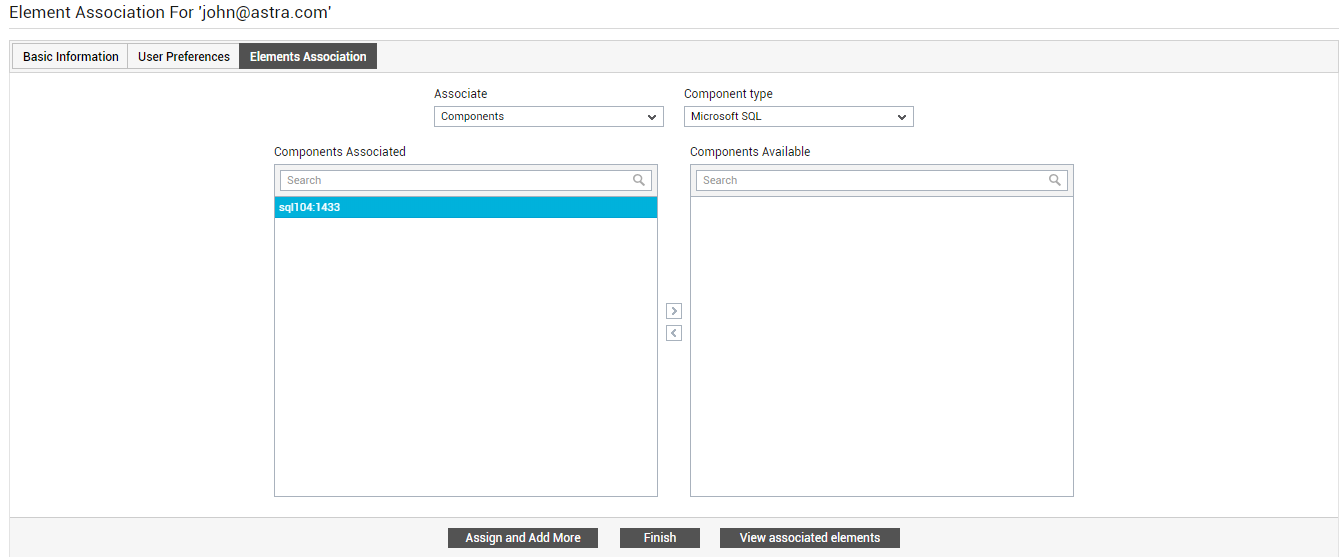
Figure 24 : Assigning the Microsoft SQL Server to the User in our example
The Tenants' View of the Monitored Environment
Let us now find out what each of the tenants in our example see when they login to the eG web console. We will begin with the banking Organization.
Figure 25 reveals the Monitor Dashboard of the Organization.
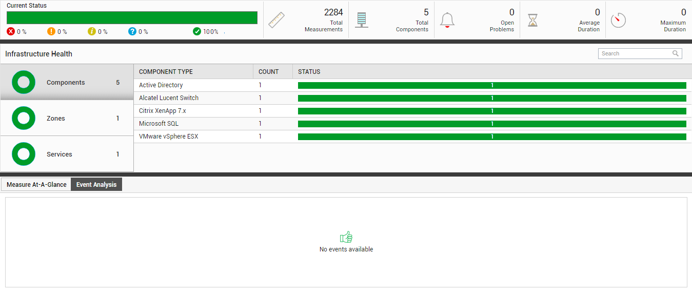
Figure 25 : The tenant Organization's monitoring view
From the Infrastructure Health section, it is clear that the following elements are part of the Organization's monitoring scope:
- One zone - This is the zone that eG Enterprise automatically creates for a tenant Organization. We had explicitly assigned this zone to the banking Organization in our example at step 18 of Creating an Organization (see Figure 17).
- One service - This is the retail banking service in our example, which we had assigned to the banking Organization (see Figure 19).
- Five components - This includes the independent component we explicitly assigned to the Organization in our example (see Figure 18). The other four components are those that are engaged in the delivery of the retail banking service. As already mentioned, when a service is assigned to an Organization, all components supporting that service will be automatically assigned to that Organization. To know which components are part of the Organization's monitoring purview, take a look at the section to the right of the Infrastructure Health section in Figure 25.
Figure 26 reveals the Monitor Dashboard of the Organizational Unit - i.e, the retail banking department in our example.
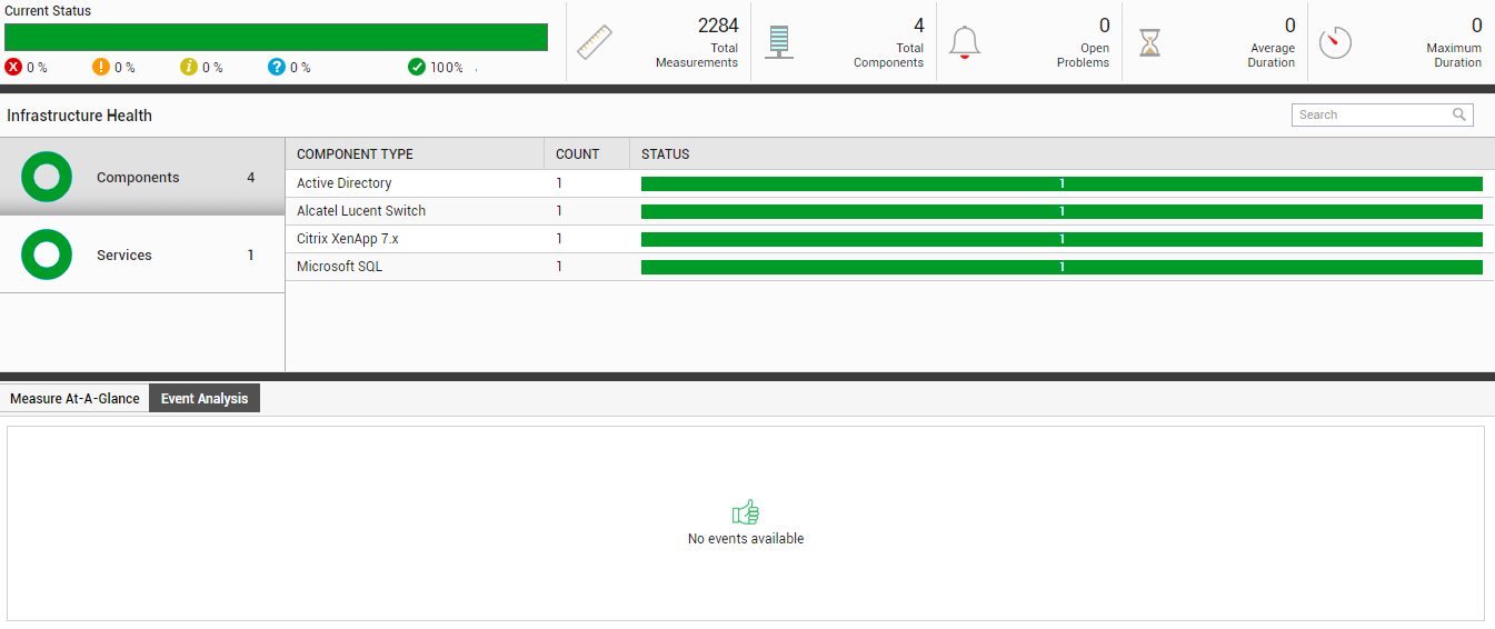
Figure 26 : The Organizational Unit's monitoring view
Since the retail banking service is the only element associated with the Organizational Unit, the Infrastructure Health section depicts the health of one service only. The four components that are part of the monitoring scope of the Organizational Unit are those that underlie the retail banking service. No other zones or components are part of the monitoring view of the Organizational Unit, as we have not assigned any other element to this unit in our example.
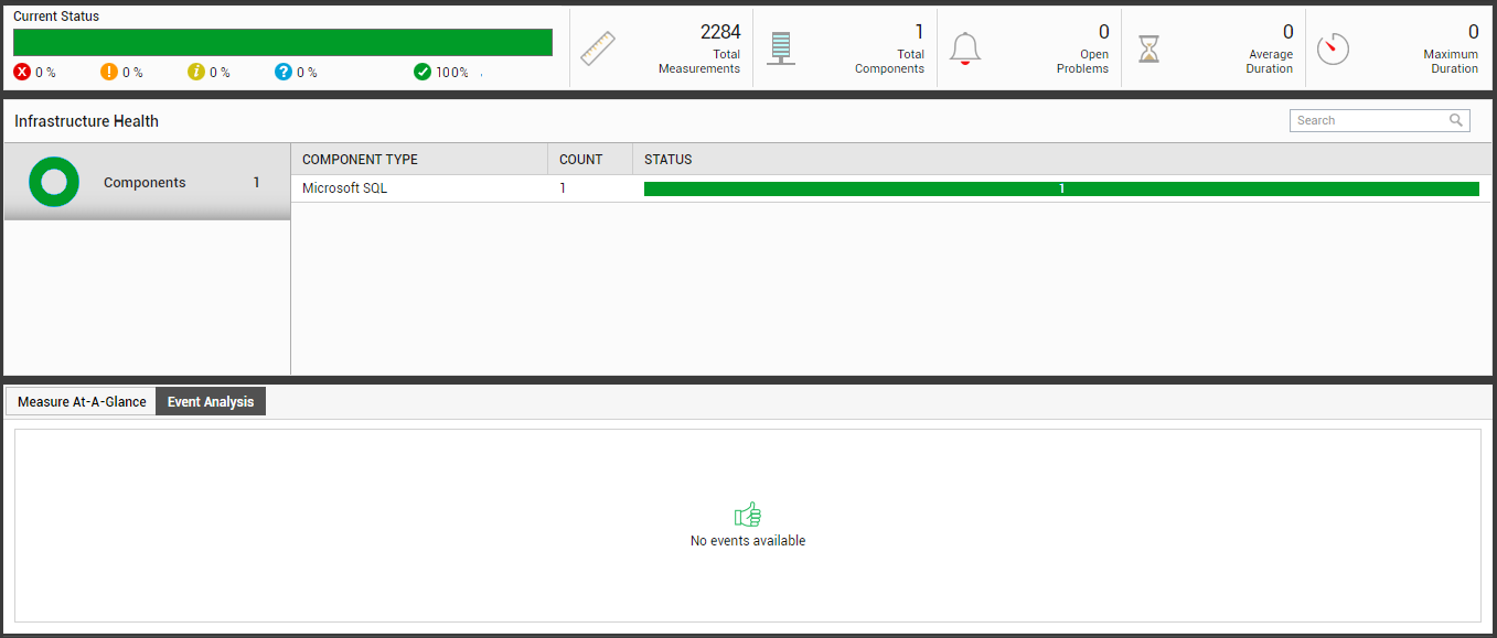
Figure 27 reveals the Monitor Dashboard of the user john we created in Creating a User.