Configuring the eG SCOM Connector
If the Launch Configuration & Setup Tool check box is selected in Figure 7, then finishing the installation will automatically launch the eG SCOM Connector configuration tool. If this check box is deselected, then, you will have to manually launch the configuration tool by following the menu sequence: Start -> Programs -> eG SCOM Connector. Either way, once the tool is launched, proceed to configure the connector using the steps discussed below:
-
Upon launching the tool, Figure 1 will appear with the SCOM Server tab page open.
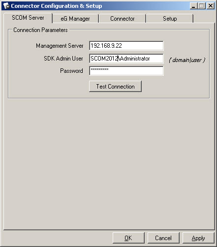
- If the eG manager is integrating with SCOM 2012/2016/2019, you can specify the IP address/host name of any management server in the environment in the Management Server text box of Figure 1.
- The eG SCOM Connector needs to connect to the SCOM SDK Service (on the SCOM server) to update the SCOM server with monitoring objects that have been newly added/removed from the eG Enterprise system, and to import and author eG management packs. To enable this connection, you need to configure the connector with the credentials of a user who is authorized to connect to the SDK service and perform administration functions. Specify the credentials of such a user in the SDK Admin User and Password text boxes. Note that the SDK Admin User has to be specified in the following format: <domainname>\<username>
-
Then, to check whether your specifications are correct, click the Test Connection button. If the eG SCOM Connector is able to connect to the SCOM server with the given specifications, then a message to that effect will appear.
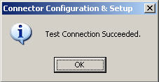
Figure 2 : Connection to the SCOM server is successful
-
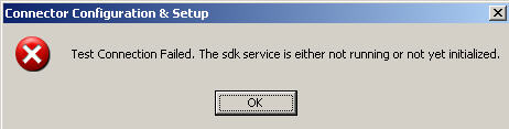
On the other hand, if the connector is not able to connect to the SCOM server, then a message indicating the connection failure and reasons for the same will appear.
-
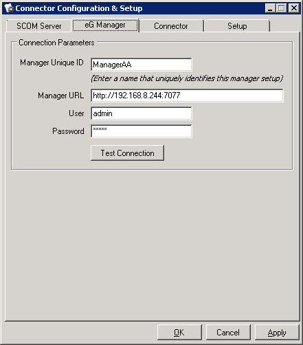
In case of a failure, first click the ok button in Figure 3 to close the message box. Then, take another look at your specifications, make changes wherever necessary, test the connectivity yet again, and if successful, proceed with your configuration. To proceed, click the eG Manager tab page in Figure 4. Typically, the eG connector polls the eG manager for discovering the managed components/layers/tests/descriptors/measures from the eG Enterprise system and inserting corresponding monitoring objects and unit monitors in the SCOM server. Using the eG Manager tab page of Figure 4, you can indicate which eG manager is integrating with the SCOM server and how to connect to it. As part of this exercise, specify the following:
-
In the Manager Unique ID text box, provide a unique ID for the eG manager with which the SCOM server will be integrating.
Note:
- Before providing the manager ID, make sure that you have not used the same ID for any other eG SCOM Connector that may be communicating with the target SCOM server.
- Ensure that the Manager Unique ID you provide does not contain any special character, other than the underscore (_).
-
In the Manager URL text box, specify the URL using which the connector should connect to the eG manager. The URL should be of one of the following formats, depending upon whether the eG manager is SSL-enabled or not: http://<eGManagerIP>:<Portno> or https://<eGManagerIP>:<Portno>.
Note:
The integration will work in a redundant eG manager setup as well. In other words, if the primary manager fails, then the SCOM connector is capable of automatically polling the secondary manager in the environment for state information.
-
Next, in User and Password text boxes specify the credentials of a user who is registered with the eG Enterprise system, and who has the right to monitor one/more components in the target environment. The components assigned to this user will only be managed by the SCOM server.
- Currently, the eG SCOM Connector does not support Active Directory group users registered with the eG Enterprise system.
- If VMs are mapped to a user registered with the eG SCOM Connector, such VMs will not be visible in the SCOM console after the integration.
- For an Enterprise deployment of eG Enterprise, ensure that the eG user account configured in the SCOM connector does not contain special characters other than Underscore (_) and Dot(.). For a SaaS deployment of eG Enterprise, ensure that the eG user account configured in the SCOM connector does not contain special characters other than At (@), Underscore (_) and Dot(.).
- If you have built custom help pages in eG Enterprise for IC-based tests and for new aggregate tests, then the Knowledge Basefeature of SCOM will not support these help pages.
- If an IC/aggregate test, measure, layer or component type in eG consists of double-byte characters (i.e., Chinese, Korean, or Japanese characters), then such tests, measures, layers, and component types will not be displayed in the SCOM console.
-
Finally, test whether the given specifications are correct by clicking the Test Connection button.
-
- Then, click on the Apply button in Figure 4 to apply the changes.
-
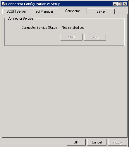
Click on the Connector Service tab page. If the connector service is yet to be installed, then the Start and Stop buttons in Figure 5 will be disabled. Also, the Connector Service Status will be Not installed (as shown by Figure 5). If the connector has been installed but is yet to be started, then the Start button alone will be enabled. You can click on the Start button to start the service and the Stop button to stop the service.
-
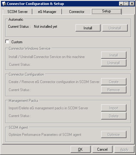
Now, click on the Setup tab in Figure 5 to execute the setup tasks. The Setup tab provides 2 options. Automatic setup will execute all the required tasks in a single action. To perform this auto setup, click on the Install button in the Automatic section of Figure 6. You can uninstall the connector at any point in time, by simply clicking the Uninstall button in the Automatic section.
On the other hand, if you wish to execute specific setup tasks, click on the Custom option and proceed as follows:
- Connector Windows Service: Click the Install button here to install the Windows service for the eG SCOM Connector, and use the Uninstall button to uninstall the service.
- Connector Configuration: The Create button here, when clicked, will create a new connector configuration for eG integration in the SCOM server. The Delete option can be used to remove the connector configuration from the server. When the delete operation is performed, all the monitoring objects discovered by the eG connector will also be deleted from the SCOM server. You can also use the Create/Delete options to cleanup and recreate monitoring objects in SCOM server.
- Management Pack: Using the Import option here, you can import the eG management pack which is stored in the connector’s installation directory into the SCOM server. The management pack includes abstract classes, relationships, monitor types, default views etc. Once the management pack is imported into the SCOM sever, the connector service will start to update it as and when new component types are discovered. The Delete option can be used to remove the eG management pack from the SCOM server.
-
SCOM Agent: In large environments where hundreds of components are managed by the eG Enterprise manager, the load on the connector would increase as it attempts to discover all the components from the eG manager. This in turn may increase the load on the SCOM agent on the connector system as well, as this agent would now be handling the hundreds of discovered components and their corresponding state changes. Under conditions of such high load, the default performance settings for the SCOM agent may not be conducive to healthy agent-connector traction. By clicking the Optimize button here, you can change the values of default parameters to the values shown in the table below:
Registry Parameter Location in Registry Value Persistence Version Store Maximum
HKLM\System\CurrentControlSet\Services\HealthService\Parameters\
65536 decimal
Persistence Cache Maximum
HKLM\SYSTEM\CurrentControlSet\Services\HealthService\Parameters\
1048576 decimal
State Queue Items
HKLM\SYSTEM\CurrentControlSet\Services\HealthService\Parameters
250000 decimal
MaximumQueueSizeKb
HKLM\SYSTEM\CurrentControlSet\Services\HealthService\Parameters\ ManagementGroups\<Management_Group_Name>
262144 decimal
Persistence Checkpoint Depth Maximum
HKLM\SYSTEM\CurrentControlSet\Services\HealthService\Parameters
52428800 decimal
These default settings are ideal for small/medium-sized environments, where only a few components are monitored - say, less than 50 components. Where the connector needs to handle a large number of components, the value of these registry entries have to be tuned further. This is because, with an increase in monitored targets, the load on the SCOM agent also increases. The agent will hence require more memory for its processing to be faster and also to avoid the following error in “Operations Manager” event log on the connector machine.
Event ID: 4506
Event Source: HealthService
Event Description: Operations Manager
Data was dropped due to too much outstanding data in rule <rulename> running for instance <instance name> with id:<instance id> in management group <management group name>.To allow the SCOM agent to utilize more memory available in the system, you can use regedit to manually set a higher value for the Persistence Cache Maximum registry entries in HKLM\System\CurrentControlSet\Services\ HealthService\Parameters\.
First, double the current value of this parameter and check if performance improves. Also, confirm that no errors are captured by the event log post this change. If no performance improvements are visible, double the value of this parameter again. Repeat this procedure until the value of this parameter is set as high as “2048000”.
With the above setting, the typical memory usage of SCOM agent processes would be around 3GB.
Also, with this value increased, the startup and stopping of the “Health Service” will take longer than normal.
Note:
The Optimize button will be disabled if the registry entries mentioned in the table above have already been set to the values prescribed above.
- Finally, click the ok button to exit the connector configuration window.