Adding a Non-Descriptor-Based SNMP Test
First, let us take the example of a Nortel (Bay Networks) switch that is available in your environment. This example involves creating a BaySwitchTest, which will use the Nortel (Bay Networks) switch’s SNMP MIB to report the number of services running on it.
Begin adding a new test by selecting the Test option from the Integration Console tile (see Figure 1). In the integration console - test page that appears next, click the Add New Test button. The new test details page (see Figure 1) appears, wherein the following details need to be provided for our example:
-
Test name – BaySwitchTest_ex
Note:
While adding a new test using the Integration Console, ensure that the Test name always ends with _ex. If not, an error message (see Figure 3) will appear upon clicking the Add button in Figure 1.
- Duplicate - Since the new test is not a duplicate of any existing test, set the Duplicate flag to No.
-
Execution – External, as an external agent will be executing the test.
Note:
Using the Integration Console plugin, you can add an internal or an external test, but you cannot add tests that need to be run by a remote agent – i.e., tests that need to be executed in an agentless manner.
- Port based – Indicate whether the target server is listening on a port or not. In our case, the Nortel (Bay Networks) switch is not listening on a port.
- Test type - Snmp
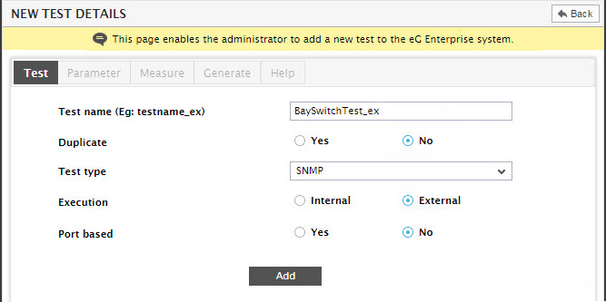
Figure 1 : Adding a new test of type Snmp
Then, click the Add button to add the new test to the eG Enterprise system. The Parameter tab page then opens automatically (see Figure 2).
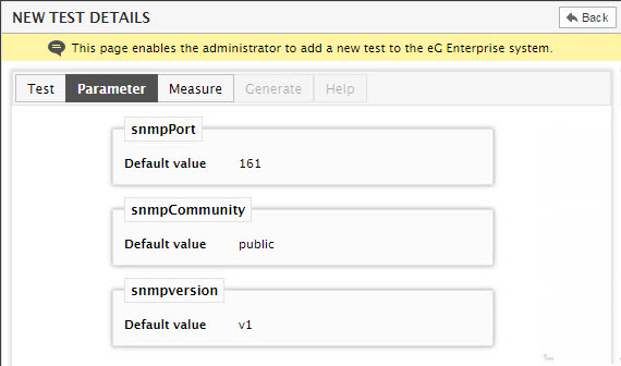
Figure 2 : Viewing a summary of the details of the BaySwitchTest_ex
Note that, unlike other test types, by default the Snmp test type takes three parameters: snmpPort, snmpCommunity, and snmpversion (see Figure 2), with default values 161, public, and v1 respectively. You cannot delete these parameters, but they can be modified. Next, proceed to configure the measures for the BaySwitchTest_ex by clicking on the Measure tab page in Figure 2.
Clicking the Add New Measure button in the Measure tab page will invoke the new measure details pop-up depicted by Figure 3. This figure shows how a measurement of the Snmp type is specified. The first measure, No_of_services, represents the number of services running on the Nortel (Bay Networks) switch. Now, enter No_of_services as the Measure name. Then, mention the Database column size, the Unit, the Conversion Factor, and the Process method as shown in Figure 3. Once again, leave the Alarm display string blank.
Note:
- To know more about the Process method, refer to Adding a Script/Batch File-based Test.
- To know more about the Conversion factor, refer to Adding a Custom Performance Test .
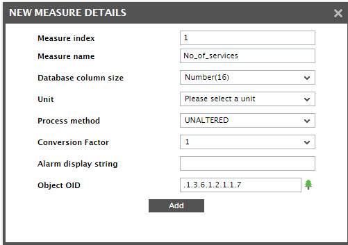
Figure 3 : Specification of the No_of_services measure for the BaySwitchTest_ex
In addition to the above, an Object OID text box exists (see Figure 3). In this text box, enter the object ID of the specified measure. This object ID can be arrived at in either of the following ways:
- By manually “walking” the MIB tree of the application or network device of interest
- By uploading the SNMP MIB file of the application/network device to the eG manager and browsing the MIB tree using the eG administrative interface
In this example, we will discuss both the methodologies.
Determining the OID using SNMP Walk
For the purpose of our example, let us use the standard MIB- interface supported by the Bay switch. The figure below depicts a part of the MIB of relevance to this example:
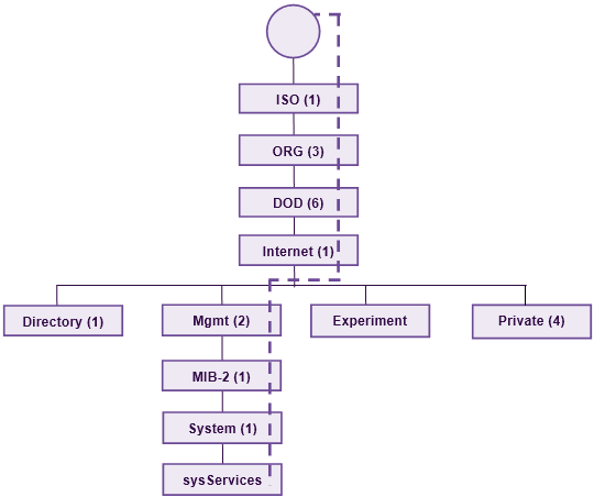
Figure 4 : A portion of the MIB tree of the Bay switch
As shown in Figure 4, the MIB tree comprises of various nodes and sub-nodes, also referred to as “objects”. Note that every object is accompanied by a numeric value. These numeric values, when put together in sequence using a dotted notation, provide the unique “object ID” of an object.
For example, the ID of the Internet object in the above tree would be: .1.3.6.1. 1, 3 and 6 are the numbers representing the objects that precede the Internet object (i.e. ISO, ORG and DOD respectively) in the MIB tree (see Figure 4). The final 1 in the object ID represents the Internet object itself. By arranging these numbers in the order of their occurrence in the MIB tree using the dotted notation, you will arrive at the ID of the Internet object.
You can arrive at the object ID of the No_of_services measure also in the same manner. The sysServices object in the MIB tree (see Figure 4) returns the number of services currently running on the Bay switch. Therefore, the ID of this object needs to be specified as the Object OID of the No_of_services measure. The dashed lines (-------) in Figure 4 trace the path from the root of the MIB tree to the No_of_services object. Now, do the following:
-
Follow the dashed lines closely and identify the objects through which the lines pass. In our example, note that the lines pass through the following objects:
- ISO
- ORG
- DOD
- Internet
- Mgmt
- MIB-2
- System
- sysServices
-
Pick the numbers representing the objects. In our example, the numbers are:
- ISO : 1
- ORG : 3
- DOD : 6
- Internet : 1
- Mgmt : 2
- MIB-2 : 1
- System : 1
- sysServices : 7
- Note the order in which the above-mentioned objects appear in the MIB tree, and arrange the corresponding numbers in the same order using the dotted notation
- You will now have the ID for the No_of_services measure, which is: .1.3.6.1.2.1.1.7.
Now, specify this ID in the Object OId text box of Figure 3.
Finally, click the Add button to add the new measure.
Determining the OID using the MIB Browser
If you do not want to use the manual procedure for deducing the OID, then, you can determine the same quickly and easily using the MIB Browser that is built-into the eG Enterprise system for browsing uploaded MIB files online.
To use the MIB browser, do the following:
-
For the purpose of our example, let us use the MIB browser for specifying the Object OID of the No_of_services measure. For that, click on the
 button next to the Object OID text box in Figure 3. The MIB Browser will then appear as depicted by Figure 5. To browse the MIB file that we uploaded, first, select it from the MIB Files list in Figure 5. The MIB Files list contains all MIB files that have been uploaded to the eG manager. If the MIB file of the Bay switch has not been uploaded to the manager yet, then click the Upload MIB button in Figure 5.
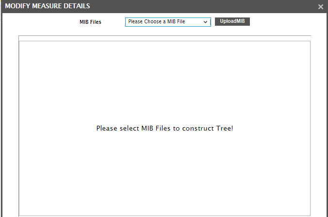
-
A pop-up window depicted by Figure 6 will then appear. In the File to upload text box, specify the full path to the MIB file to be uploaded. You can use the Browse button to locate the MIB file of interest to you.
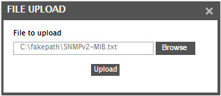
Figure 6 : Specifying the full path to the MIB file to be uploaded
- Once the MIB file path is specified, click the Upload button in Figure 5 upload the specified file to the eG manager.
-
If upload is successful, then the newly uploaded MIB file will automatically appear selected in the MIB Files list in the MIB Browser, as depicted by Figure 7. Upon selection of the MIB file, the MIB browser automatically constructs a MIB tree using the SNMP MIB object definitions in the file. To determine the OID of the No_of_services measure, drill down the MIB tree by expanding each of the nodes in the sequence, iso -> org -> dod -> internet -> mib-2-> system -> sysservices (as depicted by Figure 7 and Figure 8).
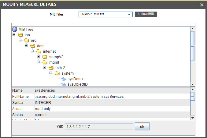
Figure 7 : The MIB Files list displaying the newly uploaded MIB file
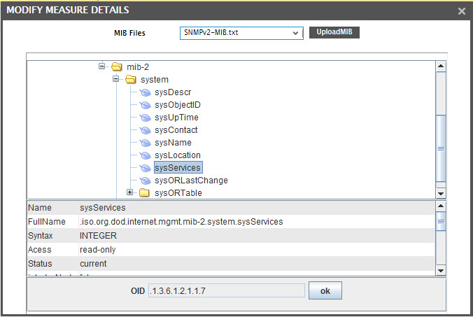
Figure 8 : Expanding the MIB tree to figure out the OID of the No_of_services measure
-
Upon selecting a node, the MIB browser automatically determines the OID of that node and displays the same against the oid field in Figure 8. Accordingly, once you drill down to the sysServices node, its complete oid will be automatically deduced and displayed against the oid field. To insert this OID into the Object OID text box in the new measure details page of Figure 3, just click the OK button in Figure 8.
You will then be prompted to confirm whether/not you want to add more measures. Click No here to stop adding more measures. This will automatically lead you to the Generate tab page (see Figure 9).
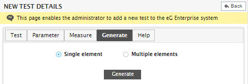
The Generate tab page of Figure 9 reveals two options: Multiple elements and Single element. To configure a descriptor-based test, select the Multiple elements option. In order to configure a non-descriptor-based test, select the Single element option. In the case of the BayswitchTest_ex, the measurements do not involve access to the SNMP table objects. Therefore, this test is a non-descriptor-based test. Hence, choose the Single element option for our example.
Finally, click the Generate button to integrate the test’s implementation into the eG Enterprise system.
When a test’s measurements are successfully configured, the eG Enterprise system prompts the user to specify the default threshold settings for each of the measurements made by the newly added test.
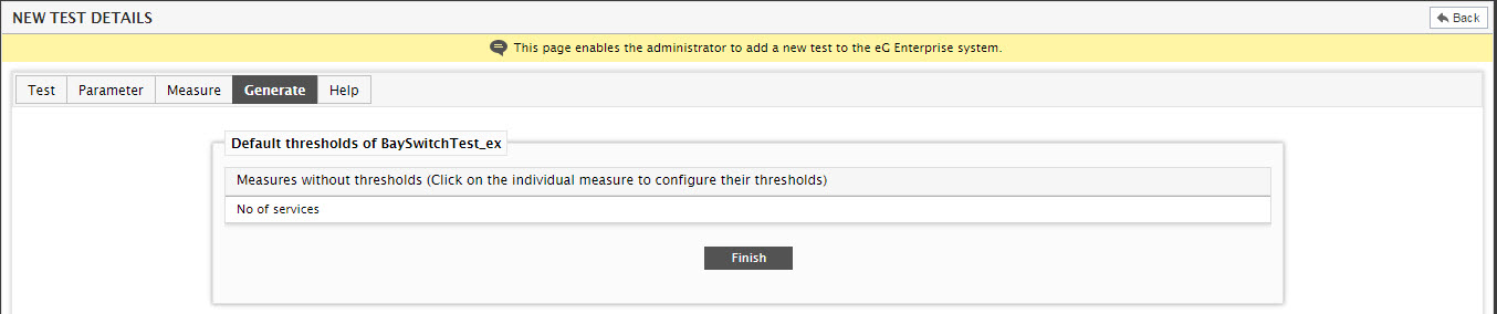
Figure 10 : Configuring thresholds for the non-descriptor-based SNMP test newly created