Viewing Component Type Health
To view the health of eG-managed component types, do the following:
-
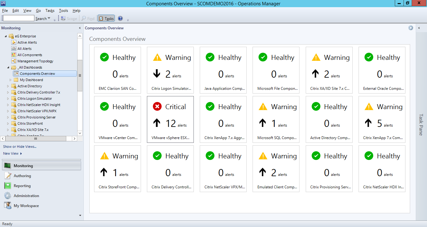
In the tree-structure in the left panel of the SCOM console, expand the _All Dashboards sub-node under the eG Enterprise node. Then, click the Component Overview node within. This will present to you a Components Overview dashboard, as depicted by Figure 1.
-
A quick glance at this dashboard, will reveal to you:
- The different types of components that are managed in eG Enterprise;
- The total number of problems that are currently open for each component type;
- An indicator (up or down arrow) as to whether the count of outstanding problems per component type has been increasing or decreasing with time. This is a good indicator to how problem-prone a component type is. This is also a good measure of the efficiency of help desk in resolving problems.
- The current state of every component type; typically, the state of the individual components of a type, determines the state of that component type. The type assumes the highest abnormal state of the underlying components. For instance, if 5 VMware vSphere servers are monitored, out of which one server is in a Critical state, 2 in the Major state, and 2 in the Normal state, the state of the component type will be Critical. This is because, Critical is the highest abnormal state.
- Problematic component types can be quickly identified using this dashboard.
-
To zoom into the health of a particular component type, expand the sub-node representing that component-type under the eG Enterprise node in the left panel. For instance, to view the health of all components of type VMware vSphere ESX in the case of our example, expand the VMware vSphere ESX sub-node of the eG Enterprise node.
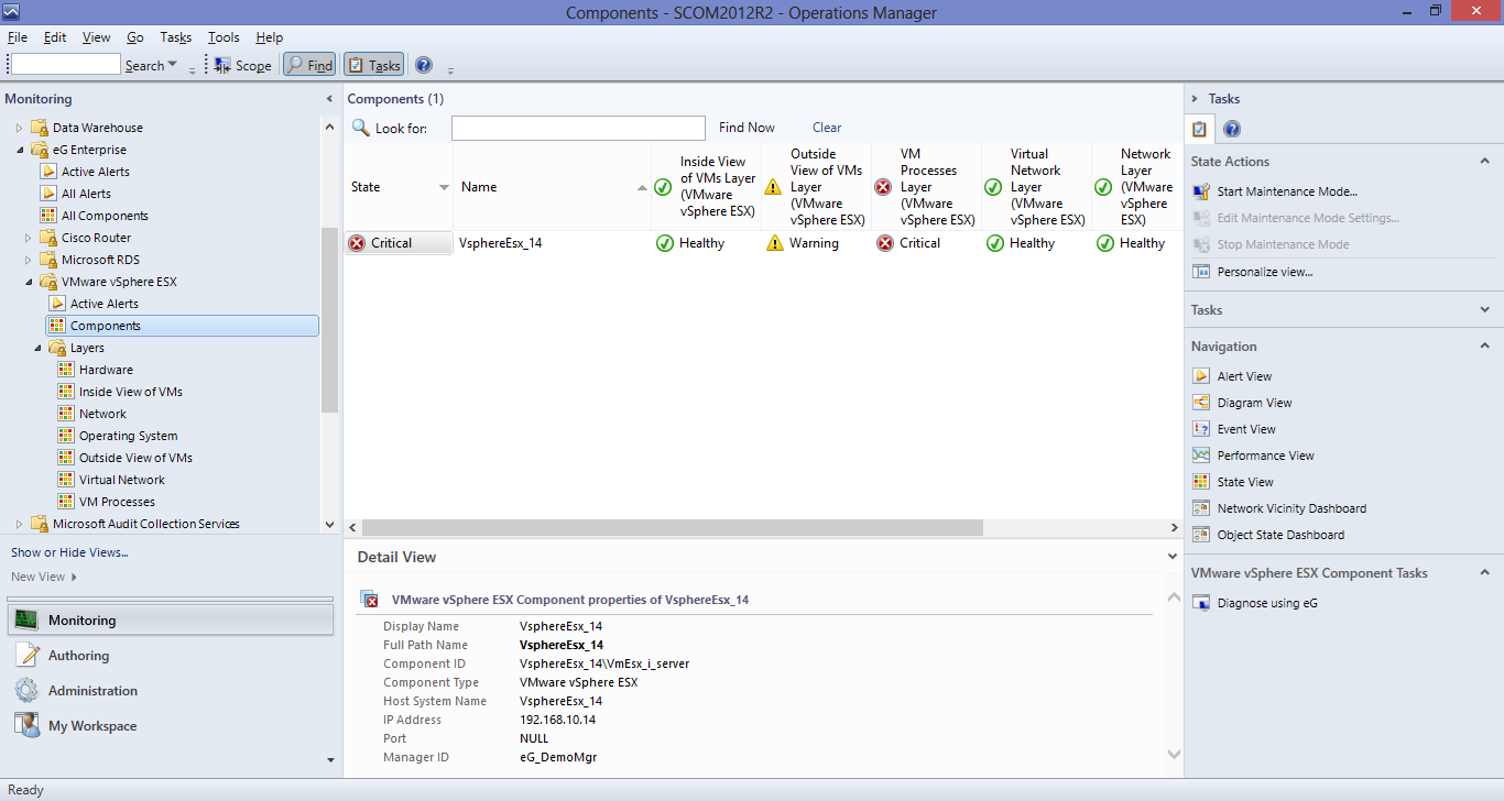
Figure 2 : Expanding the sub-node representing a component type
-
Expanding the VMware vSphere ESX sub-node will provide you with the following options:
- Viewing only the Active Alerts pertaining to the managed VMware vSphere ESX servers;
- Determining the overall health of each managed component of type VMware vSphere ESX;
- Viewing a Components Topology of the VMware vSphere ESXcomponent type, and graphically isolating the vSphere server that is performing poorly and the reason for its performance degradation;
- Exploring the health of every layer of every component of type VMware vSphere ESX, and isolating the problem layers
To view the open alarms related to VMware vSphere ESX servers, click on the Active Alerts sub-node. Figure 3 will then appear.
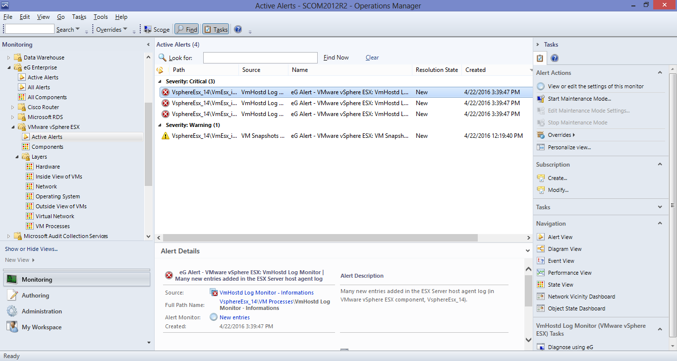
Figure 3 : Viewing the active alerts of VMware vSphere ESX servers
- In the right panel of Figure 3, you can view all the currently unresolved issues pertaining to VMware vSphere ESX servers, grouped by severity.
-
Next, if you want to know which components of type VMware vSphere ESX are currently managed and what their current states are, click on the Components sub-node under the VMware vSphere ESX node. You will then view the complete list of managed VMware vSphere ESX components and their current states in the right panel (see Figure 4).
Figure 4 : Viewing the managed components of type VMware vSphere ESX and their current state
- In addition to the component Name and State, the right panel will also display all the layers that form the layer model of the VMware vSphere ESX server, and the state of each layer for every managed VMware vSphere ESX component. This way, you can not only identify problem components, but also accurately isolate the layers that contributed to the problem.
-
To focus on the health of the individual layers, expand the Layers sub-node of the VMware vSphere ESX node. This will reveal all the layers that are part of the built-in monitoring model that eG Enterprise offers for the VMware vSphere ESX server.
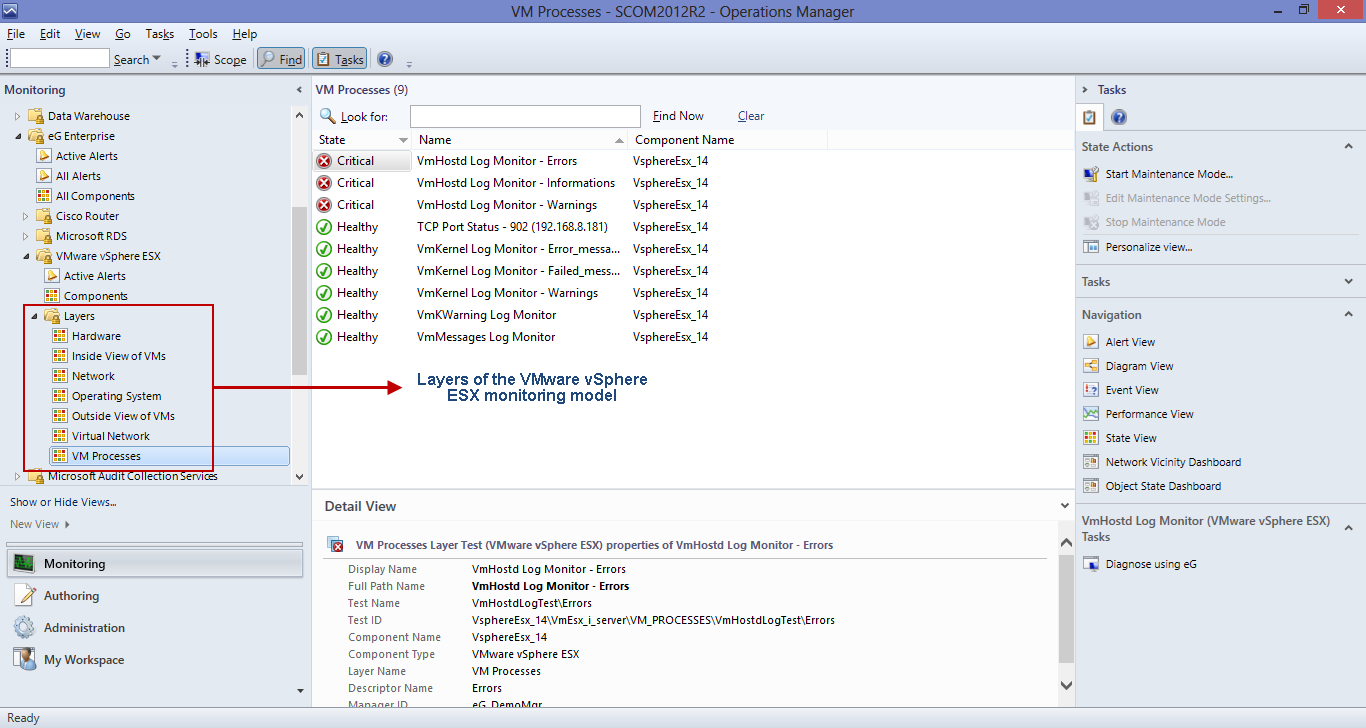
Figure 5 : Viewing the layers as sub-nodes of the 'Layers' node
- Then, click on a layer in the tree-structure. Upon clicking, all the tests mapped to that layer, the descriptors they support (if any), and the current state of each test will be available in the right panel (see Figure 5). Clicking on a row of information here will provide complete details of the test and descriptor in the Detail View below.
-
If a test is in a Critical or Warning state, you may want to know which measure of that test reported the abnormal measures and why. To zoom into the root-cause, you may want to launch the eG monitoring console from the SCOM console itself. For that, click on the Diagnose using eG option in the Actions pane of Figure 5. This will launch the eG monitoring console, where the complete layer model of the VMware vSphere ESX server will be displayed, and the problem layer, test, and measurement highlighted.
Note:
Clicking on the Diagnose using eG option will launch the eG monitoring console only if the eG Console Tasks application is installed on the system on which the SCOM console is operating. To know how to install this application, refer to Installing the eG Console Tasks Application. Also, when the eG console is launched for the very first time from the SCOM console, a login screen will appear, where you will have to manually key in the user credentials for logging into the eG monitoring console. The same credentials will be used to launch the eG monitoring console during your subsequent attempts to Diagnose using eG.
-
For a more graphical, comprehensive view of the performance of a component type, click on the Components Topology node (see Figure 6). An icon representing the VMware vSphere ESX component type will then appear. Using an intuitive icon and a conventional color code (Red), the component-type representation clearly indicates that the VMware vSphere ESX component-type is in a Critical state presently. To know which vSphere servers have contributed to this abnormal state, drill down by clicking the ‘+’ icon alongside. This will reveal all managed vSphere servers and their current state. In the case of our example, only a single single vSphere server has been managed. We can infer from Figure 6 that this vSphere server is in a Critical state presently. To understand why, click on the ‘+’ icon alongside the vSphere server (i.e., component) representation in Figure 6.
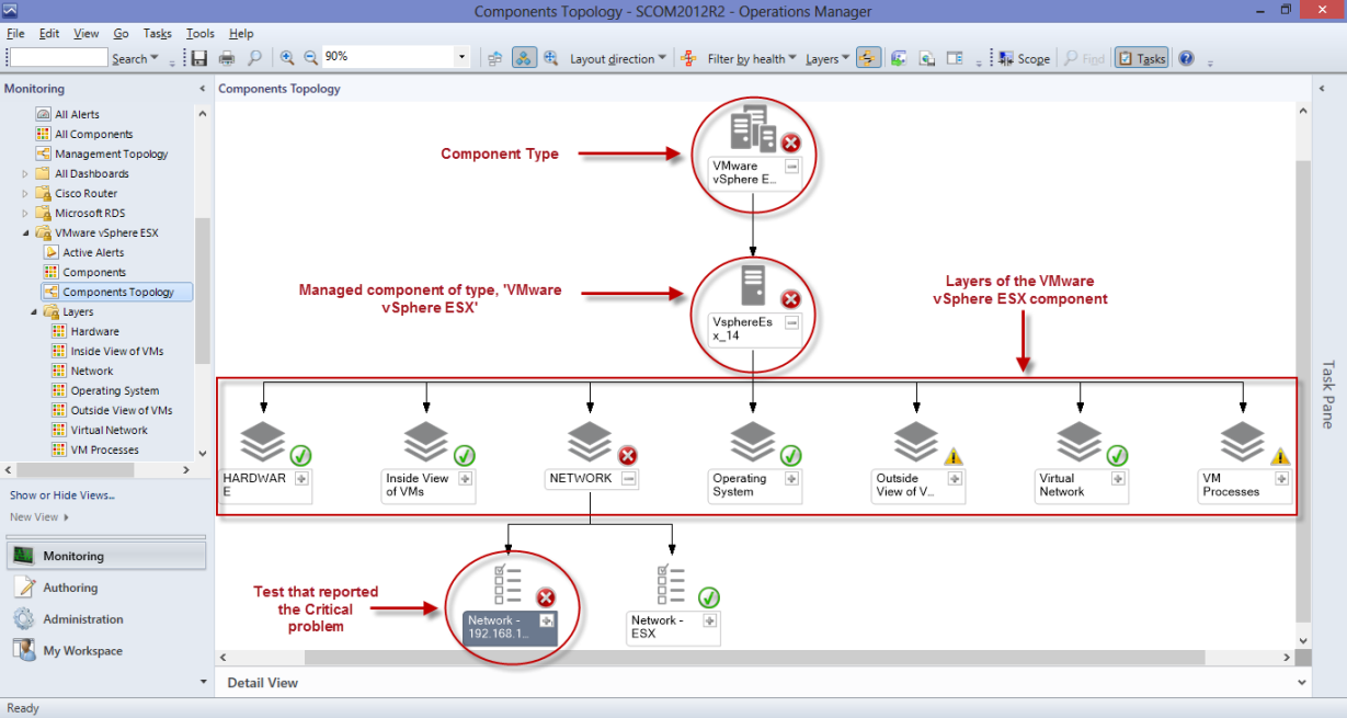
Figure 6 : The topology representation revealing the exact component of a type, layer of component, and test mapped to the layer that is a Critical state
-
This will invoke the layer model of the VMware vSphere ESX server. Each layer will be represented as a separate object in the topology and its state will be indicated. From the layer display, it is evident that the Critical issue has been detected in the network layer. If you now click on the ‘+’ icon alongside network, the tests mapped to that layer will appear, accurately pinpointing the test that captured the Critical issue. In the case of our example, the Critical issue has been reported by the Network test. To zero-in on the precise issue, right-click on the Network test representation in the topology and pick the Health Explorer option. will then appear pointing you to the exact measure that deviated from the threshold and caused the Critical problem. As can be inferred from , a high packet loss on the network link to the VMware vSphere ESX server is what led to the Critical state of the vSphere server.
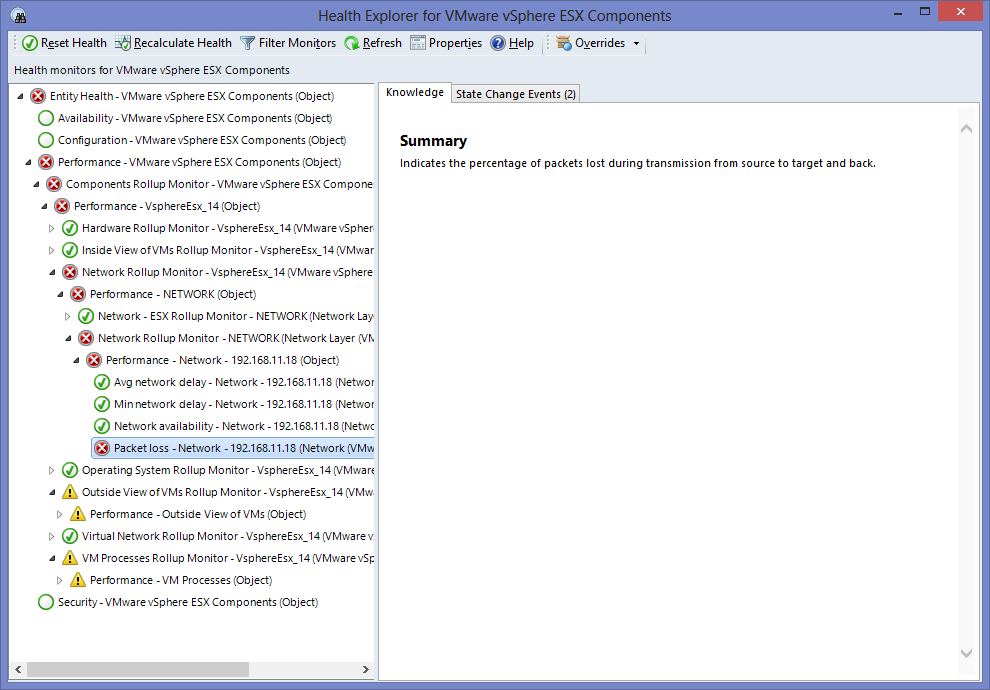
Figure 7 : Health Explorer revealing the accurate reason for the Network problem with the VMware vSphere ESX server