Building a Layer Model for a New Component Type
Let us now build a layer model for the new component-type we added in Creating a New Component-type Using the Integration Console – i.e., the Tuxedo_Domain_Server_ex. Say, the layer model of this component comprises of two pre-defined layers of the eG Enterprise system - Operating System and Network – and one user-defined layer named TUXEDO_SERVICES_ex.
To build such a model, follow the steps below:
- Click the
 button corresponding to the Tuxedo_Domain_Server_ex component in the User-defined components list of Figure 4.
 -
Figure 1 will then appear. From the Disassociated layers list of Figure 1, select the TUXEDO-SERVICES_EX layer that you want to associate with the Tuxedo_Domain_Server_ex component-type.
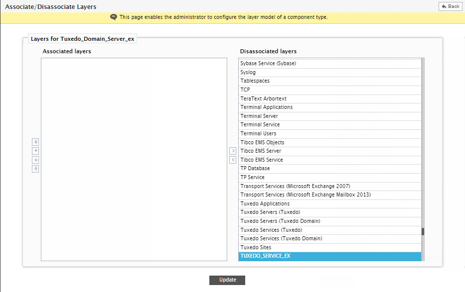
Figure 1 : Selecting the layer to be associated with the new component-type
-
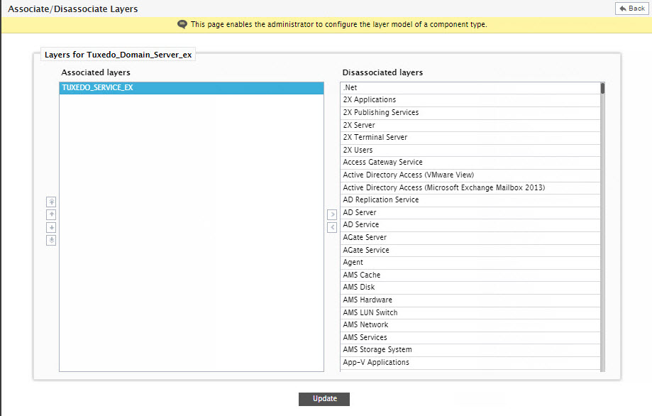
Then, click the < button in Figure 1 to move the selection to the Associated layers list (see Figure 2).
-
Similarly, associate the Network and Operating System layers too with the Tuxedo_Domain_Server_ex (see Figure 3).
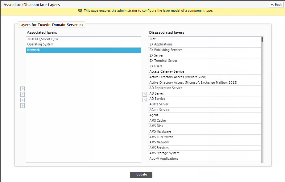
Figure 3 : Associating multiple layers with the new component-type
- If you need, you can even disassociate a layer from a component-type by selecting that layer from the Associated layers list and clicking the > button. For our example however, you need not disassociate any of the layers in the Associated layers list.
- Now that the layer model of the Tuxedo_Domain_Server_ex is complete, click the Update button in Figure 3 to save the changes.
-
Typically, layers are to be associated in the same order in which they should appear in the layer model representation in the eG monitoring console. Moreover, since state of the layers below impact the state of the layers above, exercise caution when positioning layers in your layer model. By default however, the eG Enterprise system reserves the bottom-most position to the pre-defined Operating System layer. This is why, when a new layer model is built using the Integration Console, and the Operating System layer is included in that model, eG Enterprise expects this layer to be lowest layer in the layer hierarchy. If not, the eG Enterprise system throws an exception to this effect.
In the case of our example too (see Figure 3), you can see that the Operating System layer is not the last layer. This is why, as soon as the Update button in Figure 3 is clicked, the following error message appears:
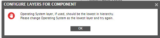
Figure 4 : An error message prompting you to change the position of the Operating System layer
-
Click the ok button in Figure 4 to close the message, and then proceed to change the position of the Operating System layer. Typically, to change the position of any layer in the layer model, you will have to use the direction buttons provided to the left of the Associated layers list in Figure 3. The table below lists these buttons and their purpose:
Direction Button Purpose 
Click to push a layer to the bottom of the layer model.

Click to push a layer to the top of the layer model.

Click to push a layer a step up.

Click to push a layer a step down.
-
To change the position of the Operating System layer in our example, select that layer from the Associated layers list of Figure 4 and click the
button. When this is done, the Operating System layer instantly swaps positions with the Network layer, thus becoming the last layer of the model. If you now click the Update button to save the changes, you will notice that the error message of Figure 4 above does not re-appear.
Note:
You can modify the layer model definition of a Pre-defined component by clicking the button corresponding to that component in the Pre-defined components panel. The rest of the procedure is the same as outlined in steps 2-9 in this section.